| |

Advantages and Disadvantages of the Bridge RectifierElectronic devices called Rectifiers change alternating current (AC) into direct current (DC). They are utilized in various applications, such as signal conditioning, electronic circuits, and power supply. This is important because AC can't be used in many electronic circuits, so the rectifier is needed to convert the AC into a DC that can be used. Rectifiers are typically made up of four diodes connected in a bridge configuration. The diodes control the current's direction so that it always flows in the same direction, which is why it converts AC into DC. The diodes also allow the current to be split into two parts, with one part flowing in one direction and the other flowing in the opposite direction. The two parts of the current are then combined so that the output of the rectifier is a DC. This DC is used for various applications, such as powering computer circuits or motors. Rectifiers can also be used to regulate the output of a DC power supply. This is done by adjusting the diodes in the bridge configuration so that the output of the rectifier is at a fixed voltage and current level. This helps to ensure that the power supply output is consistent, which is important for many applications. Rectifiers are also used for a variety of signal-conditioning applications. This means they convert signals from one form to another, such as AC to DC or digital to analog. This can be important for ensuring that signals are in the correct form for the specific application. 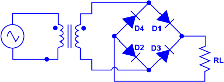
In conclusion, rectifiers are important electronic devices that convert AC into DC. They are utilized in various applications, such as signal conditioning, electronic circuits, and power supply. They are typically made up of four diodes connected in a bridge configuration, which allows the current to be split and combined so that the output is a DC. Rectifiers can also be used to regulate the output of a DC power supply and for signal conditioning applications. What is a Bridge Rectifier?An electrical component known as a bridge rectifier transforms alternating current (AC) into direct current (DC). This is done using a set of four diodes in a bridge rectifier circuit configured in a "bridge" formation to allow both positive and negative currents to flow. The bridge rectifier is used in many electronic devices, such as power supplies, AC-to-DC converters, and voltage regulators. Four diodes-two on each side-are placed in a bridge arrangement to form the bridge rectifier circuit. The diodes are connected in a way that allows them to conduct current in either direction. When AC voltage is applied to the bridge rectifier, each diode becomes forward-biased, and the current flows in one direction through the circuit. This allows the AC to be converted to DC. The bridge rectifier is a popular choice for AC-to-DC conversion because it is relatively simple, efficient, and cost-effective. It is also relatively easy to construct. The bridge rectifier can also convert higher AC voltages to lower DC voltages, which is useful in many applications. Its simple design, low cost, and ability to convert high AC voltages to lower DC voltages make it a popular choice for many applications. However, its power losses and pulsating DC output should be considered when selecting a rectifier circuit for a particular application. Construction of Bridge RectifierA bridge rectifier is an electronic circuit that combines four diodes and a transformer to convert an alternating (AC) input into a direct (DC) output. The bridge rectifier is a widely used circuit that finds application in power supplies, DC motor controllers, and many other electronic circuits. The basic operation of the bridge rectifier involves a transformer, four diodes, and a load resistor. The transformer reduces the AC voltage by a certain amount. This is afterward utilized with the four-diode bridge rectifier circuit. The two diodes on one side of the bridge form a half-wave rectifier, while the two diodes on the bridge form a full-wave rectifier. The two rectifiers are connected in series so that when the AC voltage is applied to the bridge, the two rectifiers work together to rectify the AC voltage. A pulsing DC voltage is the bridge rectifier's output. Capacitors are then used to filter the pulsing DC voltage and balance it out. The AC input, both positive and negative halves, is used to charge and discharge the capacitor. As a result, a constant DC voltage is produced as the output. The output of the bridge rectifier is then applied to a load resistor, which is used to convert the DC voltage to an appropriate level. 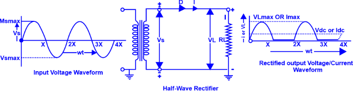
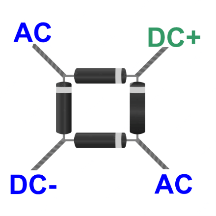
The rectifier is a widely used circuit in power supplies, DC motor controllers, and many other electronic circuits. It is an efficient, reliable, and cost-effective way to convert an AC voltage into a DC voltage. It can also handle AC and DC input voltages and rectify both positive and negative voltages. The bridge rectifier is a useful device that can be used in many applications. Diagram of a Bridge RectifierA rectifier transforms alternating current input into direct current output using four diodes. The diodes are arranged in a bridge arrangement in a bridge rectifier circuit such that the output polarity is a constant independent of the polarity at the input. Four diodes are stacked in a bridge configuration in the diagram of a bridge rectifier. 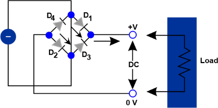
The input is connected to two diodes, while the output is connected to the remaining two. The two diodes connected to the input are called the "arms" of the bridge, while the two diodes connected to the output are called the "legs" of the bridge. When an alternating current is applied to the input of the bridge rectifier, the current will flow through two of the diodes. Depending on the polarity of the input, a switch will be created by the two diodes, enabling the current to flow in one direction while obstructing it in the other. This makes it possible to change the current from alternating to direct current. The output of the bridge rectifier will be a direct current with the same polarity as the input, regardless of the polarity of the input. This makes bridge rectifiers useful for applications requiring a constant direct current. Electric motors, battery chargers, and power supplies are just a few of the devices that use bridge rectifiers. Numerous consumer electronics, including computers, televisions, and mobile phones, also employ them. Working of a Bridge RectifierThe bridge rectifier has two input terminals, the anode and the cathode. The alternating current is applied to these terminals. The two AC input signals are out of phase, and the bridge rectifier circuit uses this phase difference to generate the DC output voltage. The diodes D1 and D3 are forward-biased, while the diodes D2 and D4 are reverse-biased when the positive half-cycle of the AC signal is applied to the anode and the negative half-cycle is applied to the cathode D1, and D3 will experience current flow, and a positive output voltage will result. Similar to this, the diodes D2 and D4 are forward biassed while the diodes D1 and D3 are reverse-biased when the negative half-cycle is applied to the anode and the positive half-cycle is applied to the cathode. The output voltage will be negative as the current passes through D2 and D4. The bridge rectifier circuit can provide full-wave rectification of an AC signal. The output of the bridge rectifier is a pulsating DC signal with a peak voltage equal to the peak voltage of the AC signal. The output voltage can be smoothed by connecting a filter capacitor across the output terminals. The filter capacitor charges and discharges with each AC signal's half-cycle, smoothing the bridge rectifier's pulsating DC output. The bridge rectifier circuit is more efficient than a center-tapped full-wave rectifier circuit because it does not require a center-tap transformer. It also has the advantage of providing a higher output voltage than a center-tapped full-wave rectifier circuit. The bridge rectifier circuit is widely used in power supplies and other applications where reliable and efficient DC power is required. It is also used in motor control circuits, where the output of the bridge rectifier is used to control the speed of the motor. 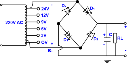
Bridge rectifiers are used in many applications, including power supplies, motor control circuits,and many other applications requiring reliable and efficient DC power. They are also used in AC/DC converters, which convert AC voltage to DC voltage. In addition, bridge rectifiers are used in many consumer electronics, such as televisions and DVD players, where they are used to convert AC voltage to DC voltage. The bridge rectifier circuit is a very simple and efficient way to convert an AC signal to a DC signal. It has the advantage of being able to provide full wave rectification without the need for a center-tapped transformer. It can provide higher output voltage than a center-tapped full-wave rectifier circuit. It is used in many consumer electronics and power supply applications because of its reliability and efficiency. Types of Bridge Rectifiers1. Half Wave Rectifier A half-wave rectifier is a type of rectifier that only allows the one-half cycle of the input AC voltage to be passed and converted to an output DC voltage. It is the simplest rectifier type and is usually used for low-power applications. 2. Full Wave Rectifier A full wave rectifier is a type of rectifier that converts both half cycles of the input AC voltage to an output DC voltage. It is more efficient than a half-wave rectifier, as it utilizes both half cycles of the input AC voltage. 3. Single-Phase Bridge Rectifier A single-phase bridge rectifier is a type of rectifier that is used to convert an alternating current into a direct current. It consists of four diodes arranged in a bridge configuration to allow both half cycles of the input AC voltage to be converted to an output DC voltage. 4. Three-Phase Bridge Rectifier A three-phase bridge rectifier is a type of rectifier that is used to convert an alternating current into a direct current. It consists of six diodes arranged in a bridge configuration to allow all three phases of the input AC voltage to be converted to an output DC voltage. 5. Double Voltage Rectifier A voltage doubler rectifier is a type of rectifier that is used to double the output voltage of the AC input voltage. It consists of two diodes, two capacitors, and two resistors arranged in a bridge configuration to allow the input AC voltage to be converted to a double-output DC voltage. 6. Voltage Multiplier Rectifier A voltage multiplier rectifier is a type of rectifier that is used to multiply the output voltage of the AC input voltage. It consists of multiple diodes, capacitors, and resistors arranged in a bridge configuration to allow the input AC voltage to be converted to a multiple-output DC voltage. 7. High-Power Bridge Rectifier A high-power bridge rectifier is a type of rectifier used to convert an alternating current into a direct current in high-power applications. It consists of four diodes arranged in a bridge configuration to allow both half cycles of the input AC voltage to be converted to an output DC voltage. 8. Forced Commutated Bridge Rectifier A forced commutated bridge rectifier is a type of rectifier that is used to convert an alternating current into a direct current in high-power applications. It consists of four diodes, four thyristors, and four inductors arranged in a bridge configuration to allow both half cycles of the input AC voltage to be converted to an output DC voltage. 9. Soft Commutated Bridge Rectifier A soft-commutated bridge rectifier is a type of rectifier that is used to convert an alternating current into a direct current in high-power applications. It consists of four diodes, four thyristors, and four capacitors arranged in a bridge configuration to allow both half cycles of the input AC voltage to be converted to an output DC voltage. 10. Multi-Phase Bridge Rectifier A multi-phase bridge rectifier is a type of rectifier that is used to convert an alternating current into a direct current in high-power applications. It consists of multiple diodes, thyristors, and capacitors arranged in a bridge configuration to allow multiple phases of the input AC voltage to be converted to an output DC voltage. Advantages of a Bridge RectifierThe bridge rectifier circuit is a full-wave rectification type that converts alternating current (AC) to direct current (DC). It is an efficient way to convert AC to DC since it utilizes both the positive and negative cycles of the AC signal. Bridge rectifiers efficiently convert AC to DC because they use diodes to convert AC to DC with minimal power loss. This makes them ideal for applications where power efficiency is important, such as solar panels or battery-powered devices. They are also relatively simple to construct, as they only require four diodes and a transformer, making them a cost-effective solution for many applications. And here are some other advantages of a bridge rectifier.
Disadvantages of a Bridge Rectifier
|
 For Videos Join Our Youtube Channel: Join Now
Feedback
- Send your Feedback to [email protected]
Help Others, Please Share


