| |

AND GateThe AND gate plays an important role in the digital logic circuit. The output state of the AND gate will always be low when any of the inputs states is low. Simply, if any input value in the AND gate is set to 0, then it will always return low output(0). The logic or Boolean expression for the AND gate is the logical multiplication of inputs denoted by a full stop or a single dot as A.B=Y The value of Y will be true when both the inputs A and B are set to true. Types of Digital Logic AND GateThe AND gate is classified into three types based on the input it takes. These are the following types of AND gate: The 2-input AND GateThis is the simple formation of the AND gate. In this type of AND gate, there are only two input values and an output value. There are 22=4 possible combinations of inputs. The truth table and logic design are given below: Logic Design 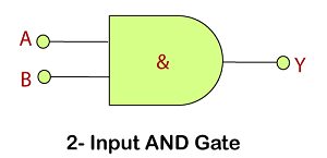
Truth Table 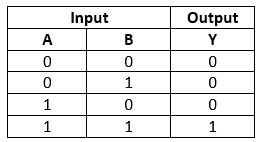
The 3-input AND GateUnlike 2-input AND gate, the 3-input AND gate have three inputs. The Boolean expression of the logic AND gate is defined as the binary operation dot(.). The AND gate can be cascaded together to form any number of individual inputs. There are 23=8 possible combinations of inputs. The truth table and logic design is given below: Logic Design 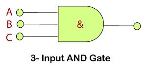
Truth Table 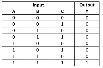
The Multi-input AND GateIn digital electronics, we can form n-input AND gate also. If there are n inputs, then (N/2)+1 AND gates will be used. For example: If we have 6 inputs A, B, C. D, E, F, then 4 AND gates are used in the logic design of 6-input AND gate. There is the following expression of the 6-input AND gate: Y=(A.B).(C.D).(E.F) In simple words, it is expressed as: Y=A AND B AND C AND D AND E AND F Logic Design 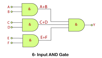
Truth Table 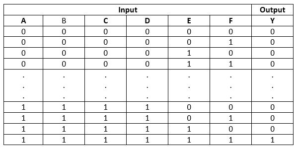
Next TopicOR Gate
|
 For Videos Join Our Youtube Channel: Join Now
Feedback
- Send your Feedback to [email protected]
Help Others, Please Share


