| |

Blinking Two LEDWe have already discussed a project of blinking an LED. Here, we will discuss a project of blinking two LED's. The concept of blinking two LED's is similar to the blinking of a single LED. As we know, we can use the resistance of any value, so let's take the resistors of 470 Ohms. The resistors reduce the amount of current reaching the LED, which saves the LED from being burnt. We can also use other resistors depending on the circuit limit and requirements. Let's start with the project. Structure of two LED'sThe structure of red and green LED is shown below: 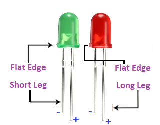
The long terminal is called Anode (positive charged), and the short terminal is called Cathode (negative charged). ComponentsThe components used in the project are listed below:
Structure of the projectHere, we will use the digital output pin number 13 and 7. The positive terminal of the red LED is connected to the PIN 13, and the negative terminal (anode) is connected to the ground. Similarly, the positive terminal (cathode) of the green LED is connected to PIN 7 and the negative terminal is connected to the ground. As mentioned, two resistors each of 470 Ohms, will be connected in series to the two LEDs in the project. The structure will represent the pinout diagram of the project. It is shown below: 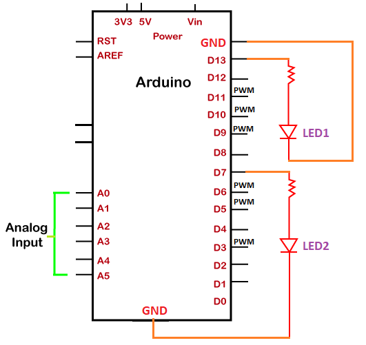
SketchOpen the Arduino IDE (Integrated Development Environment) and start with the coding, which is given below: We can modify the delay duration according to our choice or as per the requirements. The sketch will be uploaded to the board after the correct compiling, as shown below: 
Click on the Verify button present on the toolbar to compile the code. The RX and TX LED on the board will light up after the successful uploading of the code. ProcedureThe procedure to join the components of the project is shown below:
We need to check that the plug-in is performed correctly, as shown above. For any confusion, check the pin diagram shown above in the heading- Structure of project.
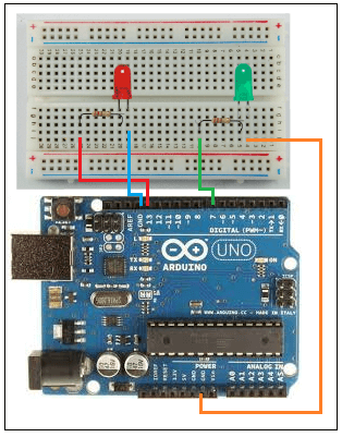
Here, the red wire is connected to the PIN 13, and the blue wire is connected to the GND. Similarly, the green wire is connected to the PIN 7, and the orange wire is connected to the GND. Note: The different colors of wire are used only for a better understanding.The shorter terminal indicates the ground. So, we will connect the shorter terminal to the Ground (GND).
It means when the red LED will be ON, the green LED will be OFF and vice versa.
Next TopicBlinking various LEDs using Arrays
|
 For Videos Join Our Youtube Channel: Join Now
Feedback
- Send your Feedback to [email protected]
Help Others, Please Share


