| |

Arduino Motion SensorWe will use a PIR motion sensor in this project. All objects (having temperature higher than absolute zero) emit radiations from the generated heat. These radiations cannot be detected by a human eye. Hence, electronic devices such as motion sensors, etc. are used for the detection of these radiations. What is a PIR sensor?The Passive Infra-Red sensors or PIR sensors detect motion or movement of an object that detect infrared radiations, such as the human body. Hence, the use of sensors is very common. The advantages of using a PIR sensor are listed below:
The PIR sensor is shown below: 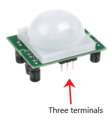
The PIR sensor has three terminals, which are listed below:
We will connect the Vcc terminal of the sensor to the 5V on the Arduino board. The PIR's sensor output can be connected to any of the digital pins on the Arduino board. The applications of the PIR sensor are automation, security systems, etc. Such sensors work great in detecting the entrance of a person in an area and leaving it. The detection range of PIR sensors is from 5m to 12m. Working of PIR SensorsThe working of the PIR sensor is entirely based on detecting the IR (Infra-Red) radiations, which are either emitted or reflected by the objects. The infrared radiations are detected by the crystalline material present at the center of the sensor. Consider a person passing in front of the background like a wall, etc. The temperature changes from room to body temperature and vice-versa within the sensor field. Changes arising in the arrival infrared radiations are converted by the sensor to the output voltage. It later detects the human body or object. Structure of PIR SensorA round metal can is mounted on the center with the rectangular crystal that detects the IR radiations. A ball like a lens present on some sensors helps in enhancing the viewing angle. The bottom part of the sensor contains many circuits mounted on it, which is shown below: 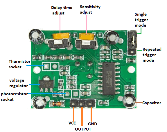
Let's start with the project. Hardware RequiredThe components required for the project are listed below:
PrincipleThe movement of jumper present on the sensor on the L side will cause a change in the state of the sensor whenever the motion is detected. Such a condition is defined as a single trigger mode. When the sensor resets the timer after every detection of motion, it is defined as repeated trigger mode. The two potentiometers present on the sensor are called as Sensitivity Potentiometer and Time Potentiometer. We can adjust both the parameters (time and sensitivity) accordingly. It should be restricted for atleast 15 seconds in front of the PIR sensor for proper calibration in the output. After 15 seconds, the sensor can easily detect movements. If any movement is detected, the LED will be HIGH. If there is no such movement, the output will be LOW. ConnectionThe steps to set up the connection are listed below:
SketchConsider the below code: Steps to upload the code to the projectThe steps are listed below:
Connection DiagramWe will show the connection using the Simulator so that the connections become clearer and more precise. We can make the same connection using the hardware devices. 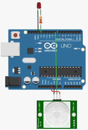
The output will be based on the detection.
Next TopicArduino Stepper motor
|
 For Videos Join Our Youtube Channel: Join Now
Feedback
- Send your Feedback to [email protected]
Help Others, Please Share


