| |

Arduino Nano PinoutThe Arduino Nano is a small Arduino board based on ATmega328P or ATmega628 Microcontroller. The Nano board is defined as a small and flexible microcontroller board. The board includes the mini USB jack to connect computer and the Nano board. The DC power jack is absent in Arduino Nano board. The Pinout of the Arduino Nano board is shown below: 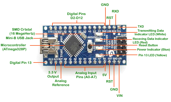
The description of pins present on the Arduino Nano board is listed below:
The Atmega328P is a high performance and low powered 8-bit microcontroller, which is based on AVR RISC Architecture. Here, AVR stands for Audio Video Recorder and RISC stands for Reduced Instruction Set Computing. It is also considered as the most popular AVR controller. It consumes less power than Atmega328 Microcontroller.
TXD and RXD pins are used for serial communication. The TXD is used for transmitting the data, and RXD is used for receiving the data. It also represents the successful flow of data from computer to the board.
The Mini USB is smaller than the standard USB but thick than the micro USB. It allows the board to connect to the computer. It is essential for the programming of the Arduino Nano board. We usually plug the USB cable in the Mini-USB jack to load the sketch to the board.
The Surface Mount crystals have better stability than other crystals. The device can be easily soldered on any board. The SMD crystal used in the Arduino Nano is of 16MHz.
It is used to add a Reset button to the connection.
It indicates the status of the battery. It can also show the voltage of the battery on the LCD display connected to the Arduino board.
There are 14 digital I/O pins. The six pins from the set of digital pins are PWM (Pulse Width Modulation) pins numbered D3, D5, D6, D9, D10, and D11. The digital pins have the value either HIGH or LOW.
There are eight analog pins numbered from A0 to A7. The function of Analog pins is to read the value of analog sensor used in the connection. It can also act as GPIO (General Purpose Input Output) pins.
The AREF pin acts as a reference voltage to feed the Arduino from an external power supply voltage.
It is defined as the input voltage, which is applied to the Arduino Board when it is using an external power source.
The 3V3 pin works as the output regulated voltage of 3.3V.
The 5V pin works as the output regulated voltage of 5V. The power source of 5V for the Arduino Nano board are USB connector, DC power jack, and the Vin. The power can be supplied to the board from either of the above specified sources.
Next TopicArduino Mega Pinout
|
 For Videos Join Our Youtube Channel: Join Now
Feedback
- Send your Feedback to [email protected]
Help Others, Please Share


