| |

Arduino Servo MotorThe principle of the servo motor is based on Pulse Width modulation (PWM). It means that the duration of pulses applied to the specific control pin controls the angle of rotation of the motor. The construction of the servo motor is similar to a DC motor. It means that it has a rotor, stator, and control assemblies. It has closed-loop feedback for controlling the torque and speed. The advantages of a servo motor are listed below:
The applications of servo motors are machinery, automated manufacturing, robotics, radio controller airplanes, etc. The controller is considered as an essential part of the servo motor. The movement in a servo motor is determined by an electric signal that can be either digital or analog. The Servo library is the library that permits the Arduino to work with servo motors. What is the Servo library, and why is it used?The servo library allows controlling the integrated shaft and gears. We can also position shaft at different angles between 0 and 180 degrees. The servo library on Arduino boards can support upto 12 motors, while on Arduino Mega board, it can support upto 48 motors. It is because servos do not interfere with the functionality of PWM pins on the Arduino Mega board. On other Arduino boards, the servo library disables the PWM pin 9 and 10 even if the servo is connected to these pins. The use of motors on Mega is also limited. It means we can use 12 motors on Arduino Mega. But, using 12 to 23 motors on the Mega board can disable the PWM functionality on the pin number 11 and 12. What is the difference between a regular motor and a servo motor?The difference between regular motor and servo motor are listed below:
What is the difference between a stepper motor and a servo motor?The difference between stepper motor and servo motor are listed below:
ProjectLet's start the project with Arduino. Here, the servo motor is simply connected to the Arduino. Hardware RequiredThe components required for the project are listed below:
Mini Servo Motor: It is defined as a tiny motor that can approximately rotate upto 180 degrees. It works similar to the usual servo motor, but smaller in size. We can also use any servo motor. The connection and procedure would be the same. PrincipleThe project allows us to control the shaft at angles between 0 and 180 degrees. We can also set the rotation of the shaft at different speeds. Servo motor has three terminals signal, power, and ground. The signal terminal is usually connected to the 5V pin of the Arduino board with the help of a wire. The ground, power, and signal wire are represented by black, green, and red colors. Structure of the projectThe structure of the connection or project is shown below: 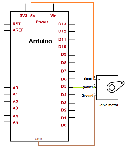
ConnectionThe steps to set up the connection are listed below:
SketchConsider the below code: Steps to upload the code to the projectThe steps are listed below:
Connection DiagramWe will show the connection using the Simulator so that the connections become clearer and more precise. We can make the same connection using the hardware devices. 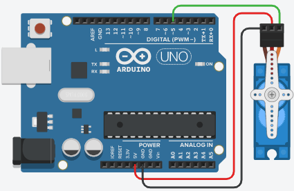
Output The shaft will rotate 90 degree in each direction i.e. approx. 180 degrees.
Next TopicArduino Servomotor using Potentiometer
|
 For Videos Join Our Youtube Channel: Join Now
Feedback
- Send your Feedback to [email protected]
Help Others, Please Share


