| |

Arduino SPIThe SPI (Serial Peripheral Interface) is a serial data protocol. The microcontrollers use the serial protocol to communicate over short distances with one or more peripheral devices quickly. The required connection of SPI is a full-duplex that allows devices to simultaneously sent and receive data. It uses four conductors for data receiving, data sending, synchronization, and device selection for communication. The SPI uses a master-slave architecture, where one Master device controls the peripheral devices. The SPI has four lines, which are listed below:
It stands for Master Input/ Slave Output. The slave line in the MISO pin is used to send the data to the master.
It stands for Master Output/ Slave Input. The MOSI and SCK are driven by the Master.
It stands for Serial Clock. These are the clock pulses, which are used to synchronize the transmission of data. In slave, it works as the input of the clock generator. In master, it works as the output clock. The data generated by the master is synchronized by the SCK.
It stands for Slave Select. It is the Slave Select line, which is used by the master. It acts as the enable line. When, SS = LOW The device interface with the master, when SS is low. SS = HIGH The device does not notice the master. It allows us to share the same MISO, CLK, and MOSI with the multiples SPI devices. The SPI is a synchronous interface that has a structure of one master and multiple slave communication. Working of SPIThe SPI uses four lines for communication that are listed above (MISO, MOSI, CLK, and SS). A master in the connection is popularly a microcontroller, and the slave can be a sensor, ADC (Analog to Digital Converter), LCD (Liquid Crystal Display), DAC (Digital to Analog Converter), etc. Let's understand the connection of the Master SPI with a slave. Consider the below examples. Example 1: Master SPI with a single slave.Consider the below image: 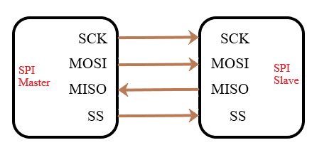
The arrow sign of MISO is in the opposite direction because it is a slave line that sends data to the master. All other lines are directed from the master only. Example 2: Master SPI with two slaves.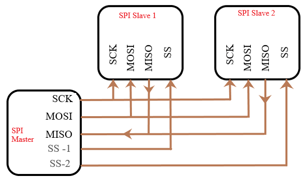
Here, the SPI Master is communicating with two SPI slaves. The individual pins of the SPI master are connected to SS of each slave. SPI PinsLet's discuss the SPI Master and Slave pins on the Arduino board. The ICSP Header includes 6 pins. The structure is shown below: 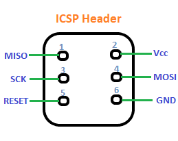
The pin number of the SPI pins is listed below: MOSI - 4 The SPI pins on different Arduino boards are listed below: Arduino UNO MOSI - 11 Arduino Due MOSI - 4 Arduino Zero MOSI - 4 Arduino Mega2560 or Mega1280 MOSI - 51 SPI LibraryThe library of SPI is: The SPI library allows us to communicate as a master device with the Arduino and the SPI devices. SPI ModesThere are four modes of SPI, which combine the clock phase (CPHA), and clock polarity (CPOL). These modes are called the four modes of transmission in SPI. The clock phase is determined as the data clock signal and clock polarity determines the idle state of the high or low signal. The SPI modes control the shifted in and out state. The state lies on the rising and falling edge of the clock polarity and clock phase. The four modes are discussed below: Mode 0 - Here, the clock polarity is 0 (CPOL = 0), while the clock phase is 0 (CPHA = 0). The data is captured at the Rising edge, and the output edge is Falling. Mode 1- Here, the clock polarity is 0 (CPOL = 0), while the clock phase is 1 (CPHA = 1). The data is captured at the Falling edge, and the output edge is Rising. Mode 2- Here, the clock polarity is 1 (CPOL = 1), while clock phase is 0 (CPHA = 0). The data is captured at the Falling edge, and the output edge is Rising. Mode 3- Here, the clock polarity is 1 (CPOL = 1), while clock phase is 1 (CPHA = 1). The data is captured at the Rising edge, and the output edge is Falling. SPI ProgrammingWe have to declare the SPI library before beginning with the SPI programming in Arduino. SPI SpeedThe SPI automatically uses the best speed, which is less or equal than the specified speed number in the SPISettings. If we are using a chip rate of 15MHz, we can use the data speed of 15000000. If we are using a chip rate of 20MHz, we can use the data speed of 20000000. FunctionsThe functions used for SPI programming are given below:
The SPI.begin() function is used to initialize the bus by setting the SS, SCK, and MOSI pins to the outputs. It pulls the lines at the state shown below: SS = High SCK, MOSI = Low The syntax is:
It is the object that is used to configure the SPI port for the particular SPI device. It includes three parameters, which are combined with this object. The syntax is: The SPISettings can be directly declared inside the SPI.beginTransaction() function if the three parameters are constant. We can create the SPISettings object if any of the settings are variables. The syntax is: where, speedMaximum = It defines the maximum speed of communication. dataOrder= LSBFIRST (Least Significant Bit First) or MSBFIRST (Most Significant Bit First). Most of the data bits in SPI uses the MSBFirst. dataMode= It includes four modes. SPI_MODE1, SPI_MODE2, SPI_MODE3, and SPI_MODE4
The beginTransaction() function is used to initialize the SPI bus by using the defined SPISettings. The syntax is:
The end() function is used to disable the SPI bus without changing the pin modes. The syntax is:
The transfer() function is used to transfer the data. We can call the function number of times.
The endTransaction() function is used to stop the bus. The syntax is:
The setClockDivider() function is used to set the clock divider with respect to the system clock. The clock in AVR boards can be divided with the available divider value of 2, 4, 8, 16, 32, 64, and 128. The default value is 4, which is represented as SPI_CLOCK_DIV4 (for example, 5MHz for the board at 20MHz). Similarly, other value will be represented. The clock in Arduino due can be divided with the available divider values from 1 to 255, where 21 is the default value. The syntax is:
The setDataMode() function is used to set the data mode in the SPISettings. The syntax is:
The setBitOrder() function is used to set the order of the bits. These bits are shifted in and out of the Serial Peripheral Interface Bus. The order of bits is set either as LSBFirst (Least Significant Bit First) or MSBFirst (Most Significant Bit First). The syntax is:
Next TopicArduino Sensors
|
 For Videos Join Our Youtube Channel: Join Now
Feedback
- Send your Feedback to [email protected]
Help Others, Please Share


