| |

Arduino UNO PinoutThe Arduino UNO is a standard board of Arduino, which is based on an ATmega328P microcontroller. It is easier to use than other types of Arduino Boards. The Arduino UNO Board, with the specification of pins, is shown below: 
Let's discuss each pin in detail.
The voltage regulator converts the input voltage to 5V. The primary function of voltage regulator is to regulate the voltage level in the Arduino board. For any changes in the input voltage of the regulator, the output voltage is constant and steady.
TXD and RXD pins are used for serial communication. The TXD is used for transmitting the data, and RXD is used for receiving the data. It also represents the successful flow of data.
The USB Interface is used to plug-in the USB cable. It allows the board to connect to the computer. It is essential for the programming of the Arduino UNO board.
It is used to add a Reset button to the connection.
It stands for Serial Clock. These are the clock pulses, which are used to synchronize the transmission of data.
It stands for Master Input/ Slave Output. The save line in the MISO pin is used to send the data to the master.
It is the modulated DC supply voltage, which is used to regulate the IC's used in the connection. It is also called as the primary voltage for IC's present on the Arduino board. The Vcc voltage value can be negative or positive with respect to the GND pin.
It stands for In-Circuit Serial Programming. The users can program the Arduino board's firmware using the ICSP pins. The program or firmware with the advanced functionalities is received by microcontroller with the help of the ICSP header. The ICSP header consists of 6 pins. The structure of the ICSP header is shown below: 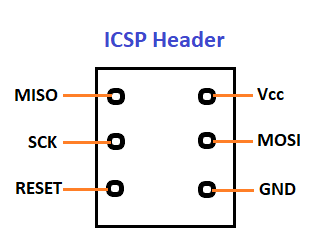
It is the top view of the ICSP header.
It stands for Serial Data. It is a line used by the slave and master to send and receive data. It is called as a data line, while SCL is called as a clock line.
It stands for Serial Clock. It is defined as the line that carries the clock data. It is used to synchronize the transfer of data between the two devices. The Serial Clock is generated by the device and it is called as master.
It stands for Serial Peripheral Interface. It is popularly used by the microcontrollers to communicate with one or more peripheral devices quickly. It uses conductors for data receiving, data sending, synchronization, and device selection (for communication).
It stands for Master Output/ Slave Input. The MOSI and SCK are driven by the Master.
It stands for Slave Select. It is the Slave Select line, which is used by the master. It acts as the enable line.
It is the two-wire serial communication protocol. It stands for Inter Integrated Circuits. The I2C is a serial communication protocol that uses SCL (Serial Clock) and SDA (Serial Data) to receive and send data between two devices. 3.3V and 5V are the operating voltages of the board.
Next TopicArduino Coding Basics
|
 For Videos Join Our Youtube Channel: Join Now
Feedback
- Send your Feedback to [email protected]
Help Others, Please Share


