| |

Armature Reaction in Synchronous GeneratorSynchronous GeneratorA synchronous generator is a device that uses electromagnetic induction to transform mechanical power into alternating current (AC) electricity. Alternators and AC generators are other names for synchronous generators. Since it generates AC power, it is referred to as an "alternator." Because it has to be run at synchronous speed in order to generate AC electricity at the required frequency, this generator is known as a synchronous generator. There are two types of synchronous generators: single-phase and poly-phase (generally 3 phase). Working Principle and Operation of AlternatorAn electromagnetic field (EMF) is created in a conductor when the flux connecting to it changes. This is the way an alternator or synchronous generator operates. When the alternator's armature winding is exposed to a revolving magnetic field, the winding will produce voltage. The alternate N and S poles develop on the rotor when the alternator's rotor field winding is powered by a DC exciter. The magnetic field of the rotor poles cuts the armature conductors mounted on the stator as the rotor is turned counterclockwise by a primary mover. As a result, electromagnetic induction induces the EMF in the armature conductors. Because the rotor's N and S poles pass the armature conductors alternately, the induced EMF is alternating. The Fleming's right-hand rule may be used to identify the path of the produced EMF, and the frequency is found by Where, The synchronous speed in RP is Ns. P is the rotor poles' total number. The rotor's rotational speed as well as the DC field excitation current both affect how much voltage is produced. When the winding is balanced, the voltage generated in each phase is the same yet differs electrically by 120° in phase. Armature Reaction in Synchronous GeneratorOn the basis of Faraday's law, every spinning electrical machine operates. Every electrical device needs a magnetic field, a coil (known as an armature), and a motion in relation to each other. When using an alternator, we provide electricity to the pole to create a magnetic field, and the armature provides the output power. The conductors of the armatures cut the magnetic field's flux due to the relative motion between the field and the armature, causing a changing flux linkage with these conductors. The armature would experience an electromagnetic field (EMF) in accordance with Faraday's law of electromagnetic induction. As a result, the armature coil starts to conduct current as soon as the load is attached to the armature terminals. As soon as current begins to flow through the armature conductor, it has one reversible influence on the synchronous generator main field flux (or alternator). The armature response in an alternator or synchronous generator is the technical term for this adverse impact. In other words, armature response refers to the interaction between armature (stator) flux and the flux generated by the rotor field poles. We obviously know that a current-carrying conductor generates one's own magnetic field, and that this magnetic field has an impact on the alternator's primary magnetic field. 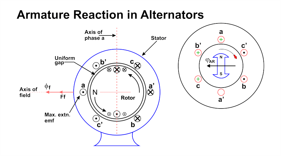
Either the main field is distorted, the main field flux is decreased, or both of these unfavorable consequences occur. They cause the machine's performance to decline. There is a phenomenon called the cross-magnetizing effect when the field is deformed. And the demagnetizing effect is what happens as the field flow decreases. The magnetic field acts as a channel for the electromechanical energy conversion. An emf, whose magnitude depends on the relative speed and magnetic flux, is produced in the armature windings as a result of the relative motion between the armature conductors and the main field. The armature reaction causes flux to be reduced or distorted, which in turn affects the net induced emf and lowers the machine's performance. Now let us see Armature Reaction in AlternatorThe impact of armature response in an alternator, like that in all other synchronous machines, depends on the power factor, or the phase connection between both the armature current and terminal voltage. When a generator powers a lagging load, it is delivering magnetic energy to the load because reactive power (also known as lagging) is the magnetic field energy. The generator's net reactive power decreases since this power is derived from synchronous machine stimulation. The armature response is demagnetizing as a result. Similar to this, the generator supplies a leading load (as the leading load absorbs the leading VAR) and in exchange receives trailing VAR (magnetic energy) from the generator, which has a magnetizing effect. The only armature reaction when the load is solely resistive is cross magnetization. The phase angle between the stator armature current and the induced voltage across the alternator's armature winding determines the armature response of an alternator or synchronous generator. Armature current and voltage have a phase mismatch between them that can range from -90 degrees to +90 degrees. Therefore we can say that angle lies between -90° to + 90°. We will look at three typical scenarios in order to comprehend the true impact of this angle on the alternator's armature reaction,
1. Armature Reaction of Synchronous Generator at Unity Power FactorThe angle between the armature current I and the induced emf E is zero at unity power factor. This indicates that the armature current and the induced emf are in phase. Theoretically, however, we are aware that the armature's induced emf results from a fluctuating main field flux that is connected to the armature conductor. The main field flux remains constant in relation to the field magnets because the field is stimulated by DC, but it would alternate in relation to the armature since the field and armature are moving relative to one another in the alternator. If the alternator's primary field flux in relation to the armature may be expressed as Φf=Φfmsinwt………(1) The induced emf across the armature is thus dΦf/dt proportional. Now dΦf/dt = -wΦfmcoswt……..(2) Hence, from these above equations (1) and (2), it is clear that the angle between, φf and the induced emf E will be 90°. Armature flux an is now inversely correlated with armature current I. As a result, armature flux Φa and armature current I are in phase. I and E are in phase at unity electrical power factor once more. As a result, at unity power factor, a and E are in phase. Therefore, at this point, the field flux and induced emf E are in quadrature, and the armature flux is now in phase with E. As a result, the armature flux a and the main field flux f are in quadrature. Due to the two fluxes' perpendicular relationship, the alternator's armature response at unity power factor is solely of the distorting or cross-magnetizing kind. The arrangement of main field flux under a pole face doesn't really stay uniform as the armature flux drives the main field flux perpendicularly. Beneath the leading pole tips, the flux density falls while it increases somewhat under the following pole tips. 2. Armature Reaction of Alternator at Lagging Zero Power FactorThe armature current lags the induced emf in the armature by 90 degrees at trailing zero electrical power factor. Since the main field flux induces an emf in the armature coil, the emf advances the main field flux by 90 degrees. The field flow is obtained from equation (1). Φf=Φfmsinwt Therefore, induced emf E ∝-dΦf/dt E ∝-wΦfmcoswt Thus, E is at its maximum and Φf is zero at time wt = 0. E is zero and Φf is at its highest value at wt = 90°. E is at its maximum and Φf is zero when wt = 180°. E is zero and Φf has a maximum negative value at wt = 270°. Here, Φf achieved its maximum value before E. So, f is 90 degrees ahead of E. Armature current I now lags E by 90 degrees and is proportional to armature flux a. Thus, Φa lags E by 90 degrees. As a result, armature flux and the field flux have an exact opposite effect. As a result, the alternator's armature reaction at lagging zero power factor is wholly demagnetizing. This implies that armature flux impedes main field flow directly. 3. Armature Reaction of Alternator at Leading Power FactorAt conditions of leading power factor, armature current "I" trails induced emf "E" by a 90° angle. Once more, we've demonstrated that field flux f leads to induced emf E via a 90° angle. Once more, armature flux an is inversely correlated with armature current I. As a result, Φa and I are in phase. As a result, armature flux Φa leads E by 90 degrees, just as I do. Field flux and armature flux are considered to be in the same direction in this example since they both induce emf E at a 90° angle. As a result, the combined flux of the armature and field is easily calculated. Consequently, it may be concluded that the alternator armature response caused by a wholly leading electrical power factor is of the magnetizing kind. Nature of Armature Reaction
Next TopicArmature Reaction in DC Machine
|
 For Videos Join Our Youtube Channel: Join Now
Feedback
- Send your Feedback to [email protected]
Help Others, Please Share


