| |

AutoCAD DisplayThe 2D and 3D drawings are created on the given screen. The display contains all the tools and icons which make the process to create any drawing. There are particular shortcuts for icons. The drafting is a technology for the design, which replaced the manual drafting with the automated process. Some of the icons are different on the 3D display than the 2D display. The icons of AutoCAD are present on the Ribbon Panel and the Status bar. The display of AutoCAD 2D is shown in the image below: 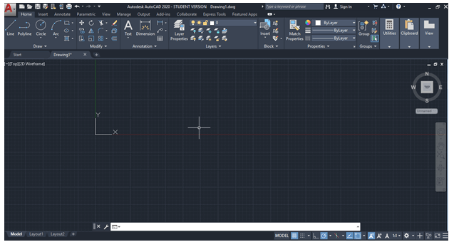
The AutoCAD 3D has two 3D displays.
The 3D Modeling includes some advance icons, while 3D Basics includes basic icons. The display of AutoCAD 3D Modeling is shown in the image below: 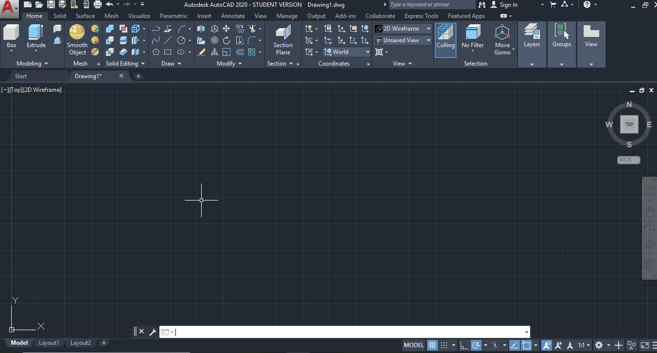
The display of AutoCAD 3D Basic is shown in the image below: 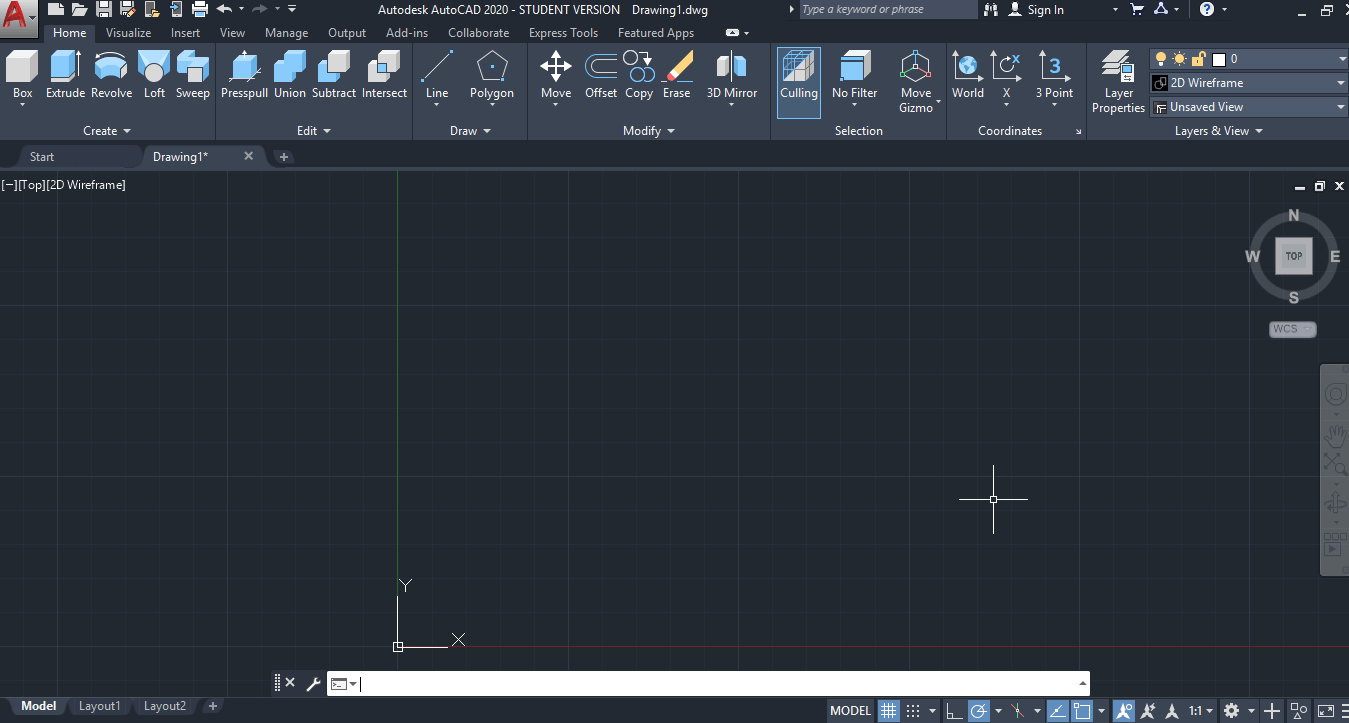
The parts of the screen are numbered for better understanding. The numbered screen is shown in the below image: 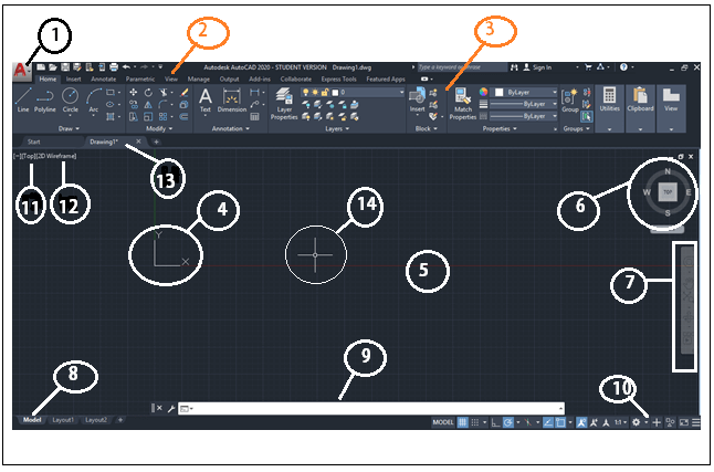
The parts of the AutoCAD 2020 display are displayed in the numbers. The name of the numbered parts are listed below: 1. Application menu/button. It is present at the upper-left corner of the workspace. To close the application menu, we can click anywhere outside the application button or window. The button is shown in the image marked as number 1.2. Quick Access Toolbar The Quick Access Toolbar is located at the top of the application window and right of the application menu. It consists of the set of frequently used commands. We can add and remove the commands according to the requirements. 3. Ribbon Panel It provides access to the dialog box related to that panel. If the ribbon panel disappears, then we need to enter the 'ribbon' on the command line to display the ribbon panel on the workspace. 4. User Coordinate System (UCS) The UCS is the active coordinate system that represents the XY plane in 2D and XYZ planes in 3D. It acts as the direction in the X, Y, and Z-axis for drawing and modeling. We can control the origin and orientation of the UCS to make drawings according to the specific points and coordinates. We can also work with drawing aids such as Grid and the ortho mode. The 2D UCS is shown in the given image: 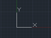
The 3D UCS is shown in the given image: 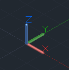
5. Model Space / Work Space / Drawing Window It is defined as the area to create 2D and 3D drawings, models, and objects. We can create using different commands according to the requirements. 6. View Cube The View Cube is termed as the navigation tool that is displayed when we are working on a 2D or 3D model space. We can switch between the isometric view and the standard view of our drawings or model. 7. Navigation Bar The Navigation Bar is used to access the navigation tools. It is a user interface element, where we can access both unified (common tools) and product-specific tools (unique product tools). The navigation bar is shown in the below image: 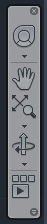
8. Model Layout Tab A layout is defined as a 2D working environment for creating the drawing sheets. The model tab is the screen where we create the 2D and 3D drawings. If the model and layout tab is not visible, then follow the steps given below: a. We need to click on the AutoCAD option displayed on the top left corner of the screen, shown as b. Click on the 'Options' button at the bottom. c. Then on the 'display' option on the top, select the option 'Display Layout and Model tabs' and then click 'Ok' as shown below: 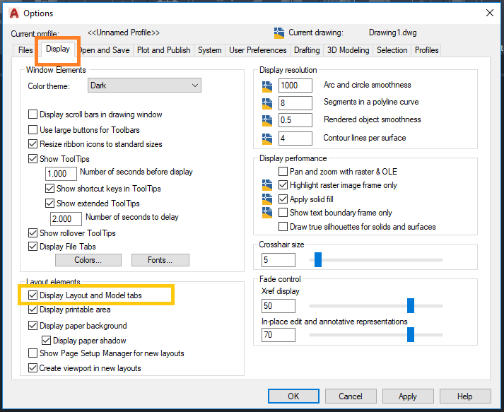
9. Command Line Window (shortcut key- ctrl+9) The command line window is used to write the commands. We need to press 'Enter' after typing any particular command. The AutoCAD also displays the steps after each command on the Command line. We need to select the option and press 'Enter' after each step. 10. Status Bar The status bar displays the drawing tools that affect the drawing environment. It provides quick access to most of the commonly used drawing tools. It includes options such as ISODRAFT, ORTHOMODE, AUTOSNAP, OSNAP, etc. 11. View Control The View Control is displayed on the left corner of the viewport. It provides a suitable way to change views, visual settings, and styles. It includes options such as top, bottom, left, right, etc. 12. Visual Style Control The Visual Style Control is the customized setting that controls the structure view of the models or 3D drawings created on the Viewport. The options include 2D Wireframe, Realistic, Shaded, Conceptual, Hidden, etc. We can also enter the visualstyles on the command line to display the options of the visual style control. After entering on the command line, the box will appear displaying clear information with figures for each option. It is shown in the below image: 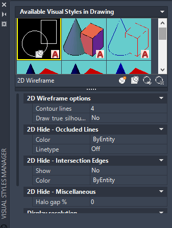
13. File Tab The file tab consists of the current drawing files opened on the screen. We can also type FILETAB command in the command line to turn on turn on the file tabs. To close the file tab, we can type FILETABCLOSE command in the command line window. We can click on the '+' sign to add a new tab on the File Tab.14. Mouse Cursor The cursor used to draw figures, etc. is known as the mouse cursor. The cursor in 2D is shown in the given image: 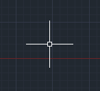
The cursor in 3D is shown in the given image: 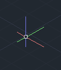
2D to 3DThe steps to convert the 2D display of AutoCAD into 3D are listed below:

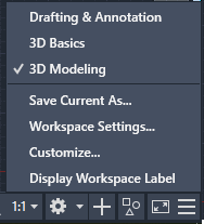
We can select 3D Modeling or 3D basics according to the requirements. The 3D modeling will include advance commands to create 3D models. The 3D Basics will include basic icons.
Next TopicAutoCAD Versions
|

 For Videos Join Our Youtube Channel: Join Now
Feedback
- Send your Feedback to [email protected]
Help Others, Please Share


