Line Command
The line in AutoCAD is drawn by specifying the starting and ending point through the cursor.
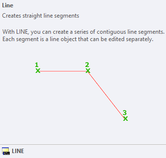
When we place the cursor on the Line icon, a window appears as shown in the below image:

The window here will specify the characteristics of a line.
The steps to create a line are listed below:
- Open the AutoCAD software.
- Select the Line icon from the ribbon panel or type L or Line and press Enter on the command line.
The line icon will look like the given image:

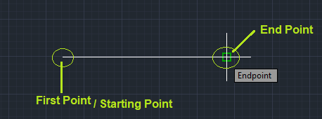
- Specify the starting point and endpoint using the cursor on the workspace or drawing area, as shown in the below image:

We can also continue the line segments by specifying the endpoints.
- Press Enter or Esc to exit.
Line using Coordinates
The steps to create a line by specifying the coordinates are given below:
- Open the AutoCAD software.
- Select the Line icon from the ribbon panel or type L or Line and press Enter on the command line.
The line icon will look like the given image:

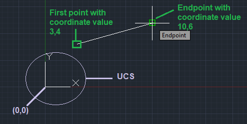
- Type the coordinate value for the first point in the form of X-coordinate, Y-coordinate.
For example, 3, 4
The value of the x-axis and y-axis will be determined with respect to the UCS icon. So we can place the UCS according to the requirements.
- Now, type the coordinate value for the second point or endpoint. For example, 10, 6.
- The line created is shown in the below image:

We can continue the line segment by specifying other points.
- Press Enter or Esc or Spacebar to exit.
Line using Angle
The left angle bracket (<) represents the angle. We need to move the cursor in the corresponding direction for the angle indication. For example, 50 degrees will be represented as <50.
The steps to create a line with a specific angle are given below:
- Open the AutoCAD software.
- Select the Line icon from the ribbon panel or type L or Line and press Enter on the command line.
The line icon will look like the given image:

- Specify the first point. We can specify it by using the coordinates or by randomly using the cursor. For example, 4, 5.
- Enter the polar coordinates in the form of length, and angle. For example, 7<55. Here, 7 is the length of a line, and 55 is the angle.
The angle will be drawn w.r.t the previous point.
- Press Enter or Esc or Spacebar to exit.
- The created line with a specific angle is shown in the below image:

We can continue the line segment by specifying other coordinates.
- Press Enter or Esc or Spacebar to exit.
Line using Relative Coordinate
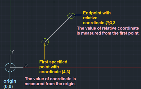
The relative coordinate is represented using @ symbol. For example, @4, 5. It measures the value from the current point.
It is also used when the dynamic input is off.
The steps to create a line using the relative coordinates are listed below:
- Open the AutoCAD software.
- Select the Line icon from the ribbon panel or type L or Line and press Enter on the command line.
The line icon will look like the given image:

- Specify the first point. We can specify it by using the coordinates or by randomly using the cursor. For example, 4,3.
- Specify the endpoint as the relative coordinate. For example, @3, 3.
- The line will appear as the below image:

We can continue the line segment by specifying other coordinates.
- Press Enter or Esc or Spacebar to exit.
What is the difference between relative (@5, 4) and (5, 4)?
The (@5, 4) measures the distance from the current point, while (5, 4) is the value measured from the origin.
Let's consider an example.
The endpoint formed by typing two times @2, 4 from the origin will be 4, 8. We can use any specified point instead of origin.
The endpoint formed by typing two times 2, 4 from the origin will be 2, 4 only. We cannot use any specific point, because the distance will be calculated from the origin only.
|

 For Videos Join Our Youtube Channel: Join Now


