| |

AutoCAD Ortho and Polar modeOrtho ModeThe Ortho mode in AutoCAD is used to restrict cursor movement to specific directions. It allows the cursor movement only in the vertical and horizontal direction. When we create, modify, or move the drawings, the ORTHO mode is used to restrict the movement relative to the UCS (User Coordinate System). The Ortho Mode is present on the Status bar at the bottom, as shown below: 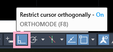
We can implement ortho mode in 2D as well as 3D. We can turn ON or turn OFF ortho mode while editing or creating drawings accordingly. We can also use ortho mode to copy or move objects horizontally or vertically. Note: To create drawings in a direction other than 90 degrees, we can use Polar Tracking. It is because Polar tracking is not restricted to specific directions.Polar ModeThe Polar Mode or Polar Tracking mode in AutoCAD restrict the cursor movement to certain angles. It displays the polar angles followed by the alignment paths. The Polar Mode in 3D provides an additional alignment in the upward and downward direction other than polar angles. The Tooltip, which is present near the cursor displays the distance and the angle. Note: Only one mode can be used at a time from the ORTHO and POLAR mode.The Polar Tracking is present on the status bar at the bottom, as shown below: 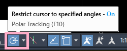
From the drop-down list of Polar Tracking, we can choose the angles according to the requirements. Let's understand with few examples. Example 1: The image is shown below: 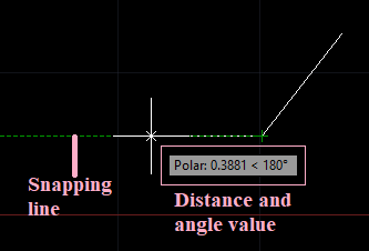
Example 2: The image is shown below: 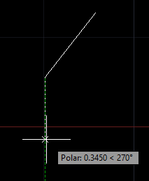
Example 3: The image is shown below: 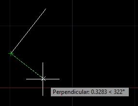
Next TopicTool Palette
|
 For Videos Join Our Youtube Channel: Join Now
Feedback
- Send your Feedback to [email protected]
Help Others, Please Share


