| |

Break command in SolidworksCross breaks are employed in HVAC or ductwork design to strengthen sheet metal. You may graphically illustrate a cross break in a sheet metal item by using the Cross Break command. The geometry of the portion is unaffected by the cross break since it is not a geometric object. You include it to provide the manufacturing process the data it needs to make the cross break. Features of a cross break
To add unique graphics and material breaks to your SOLIDWORKS models, use the Split Line tool. This procedure explains how to use Split Line to create graphics for a toy automobile model. In the SOLIDWORKS Sheet Metal course, we occasionally get asked how to incorporate a 3D cross-break. The SOLIDWORKS Cross-Break command on the Sheet Metal toolbar appears to have the functionality, however upon closer study, the cross break it inserts is simply ornamental. Since the distortion on the real component will be small, this will be adequate for the majority of applications. The geometry is kept basic by SOLIDWORKS handling it this way, which contributes to better system performance without making too many functional compromises. Because the cross break is still depicted on the drawing in the bend notes, it will still be completed on the shop floor. 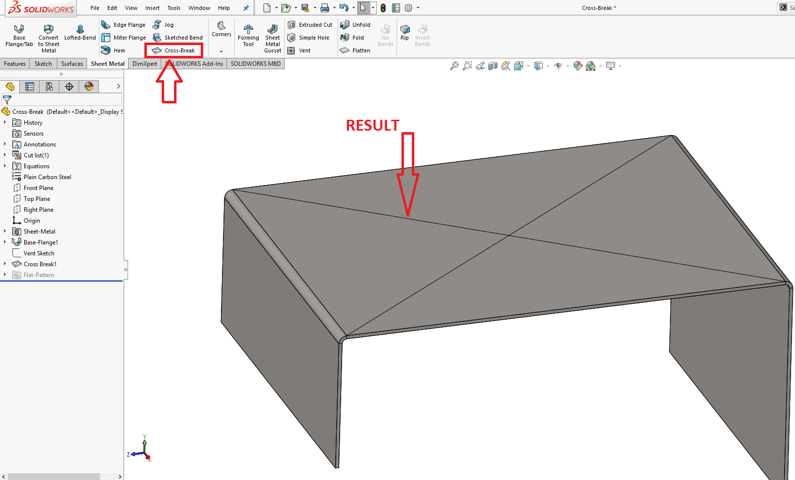
But it doesn't break down the top face, and it doesn't give me the faint pyramid form I would anticipate seeing in the actual world. Let's say I needed to demonstrate that since it was critical to my design objective. How should I approach accomplishing this? Sketched Bends and Edge Flanges are both ineffective for this. I have two bent lines that cross each other to explain why. Fortunately, there is a method for accomplishing this without utilizing bends or flanges. To accomplish what I'm trying to do, I must utilize a forming tool. I quickly gauge the size of the rectangle I'm attempting to cross-break (in this example, 150mm x 195mm). I next make a new section and sketch the 150 x 195-inch rectangle as seen below: 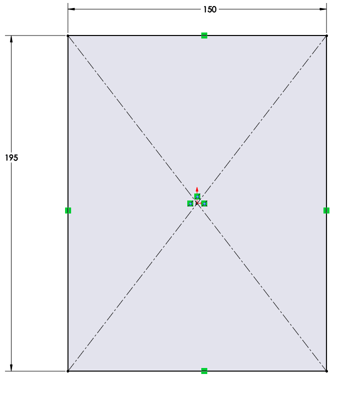
If it were a square, I could just pick the Draft option on a Boss-Extrude, but if it's a rectangle, I won't have all the faces convergent on one point. I could do a straightforward Boss-Extrude and then use the Draft command to apply draught, but I would need to use trigonometry to obtain the necessary angle, and if my rectangle size changed, I would need to redo all of my work. I'm going to switch over and utilize the Lofted Boss/Base command. You must be thinking how I can accomplish this as I require two drawings. I'm going to create a second drawing (on an offset plane, of course) that has a single point in order to convert this rectangle profile into a single point. Behold: 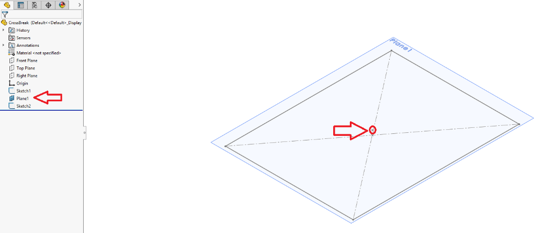
I currently have two profile drawings (even though one of them is just a single point). I can now use the Lofted Boss/Base command to crease my loft feature. This results in the formation of my extremely flat pyramid, which I will then utilize as a shaping tool to create my 3D Cross-Break. If you don't know how to make a forming tool, please read this forming tool blog article, which clearly outlines the methods. Please be aware that nothing should be chosen for Faces to Remove, and that the Forming Tool Stopping Face will be the pyramid's flat base. You may go back to your sheet metal part and utilize it once you have your forming tool. Use the Position tab to carefully find the shaping tool as seen below: 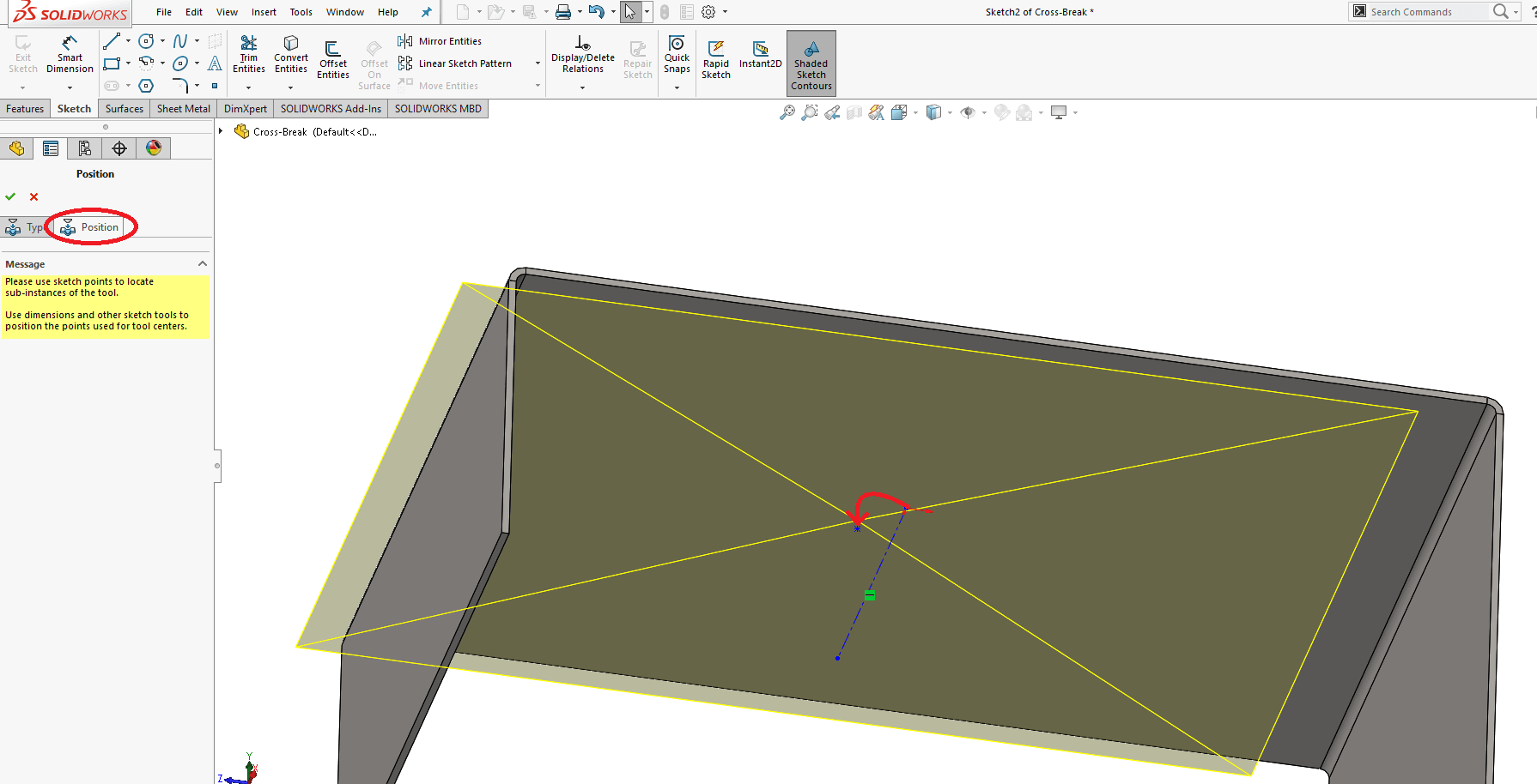
I then use the edges' midpoints as the reference points for the horizontal and vertical sketch relations: 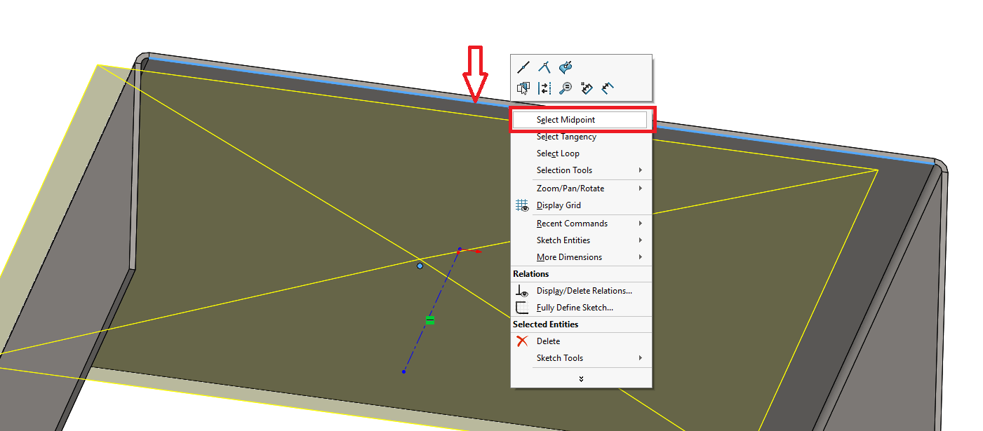
Next TopicBlock command in Solidworks
|
 For Videos Join Our Youtube Channel: Join Now
Feedback
- Send your Feedback to [email protected]
Help Others, Please Share


