| |

CALL Instructions and Stack in AVR MicrocontrollerCALL can be described in the form of a control transfer instruction. With the help of CALL instruction, we are able to call a particular subroutine. A block of instructions is contained by the subroutine. These types of instructions will be frequently executed with the help of subroutine. Because of this subroutine feature, the program will become more structured, and it will also save a lot of memory space. The AVR (Alf and Vegard's RISC processor) microcontroller contains the four types of instruction to call a subroutine, i.e., CALL (call subroutine), RCALL (relative call subroutine), ICALL (indirect call to Z), and EICALL (extended indirect call to Z). CALL InstructionThe CALL instruction is 4-byte. The opcode is represented with the help of 10 bits, and the address of a target subroutine is represented with the help of 22 bits, just like the JMP instruction. For the AVR, it provides the 4M address space of 000000-$3FFFFF. It has the ability to call subroutine at the provided range of address. After the execution of subroutine, it is not compulsory that AVR know the address where to come back. So the address of the instruction is saved by the microcontroller on the STACK, which exists just below the CALL instruction. When the execution of a subroutine is completed, the control will be transferred back to the caller with the help of RET instruction. Hence, at the end of a subroutine, the RET instruction must be placed every subroutine. STACKSTACK is a type of frequently used area of memory, which is used to temporarily store the information of a register. When we call the subroutine, it will return the address. It is a part of RAM (Random access memory) of CPU (Central processing unit). There are a few registers that's why the CPU always requires this storage space. When we call a function, the value will be stored in this temporary storage (Stack). With the help of a scratch register, we cannot store the values because they can be changed by the function. There is also a stack pointer (SP) register that can be used to access the stack. We can implement the stack pointer (SP) in the I/O memory space with the help of two registers, i.e., SPH (high byte of stack pointer), SPL (low byte of stack pointer). Stack works on LIFO (last in first out) method. That means the retrieved last value will be popped out first from the stack. When something is pushed into the stack, that stack will grow up into the higher address. When something is popped from the stack, it will decrease. 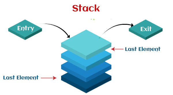
There will be two 8 bit register if AVRs (Alf and Vegard's RISC processor) contains more than 256 bytes. The stack pointer will be made of SPL only if AVR contains the memory with less than 256 bytes because the register with 8 bit is able to address only 256 bytes of memory. There is also a PUSH operation, which is used to store the information of CPU on the stack. There is also a POP operation, which is used to load the contents of a stack back into the CPU. These PUSH and POP operations are the most common and simplest way to use the stack. Now we will describe the Push and Pop operations separately. Pushing onto the STACKPushing can be referred to as "placing something at the top of stack". In the beginning, SP has the ability to point to the top of the stack. It basically stores the 64-bit register or a constant onto the stack. The registers "rax" or "r8" are known as the 64-bit register, and "eax" or "r8d" are known as the 32-bit register. When we try to push or add the data onto the stack, it will always save at the place where a stack pointer is pointing. After that, the stack pointer will be decremented by 1. For example: In the below example, we will use a PUSH instruction to push a register into a stack. The command to do this is described as follows: 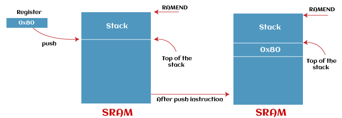
Popping from the STACKPopping can be referred to as "taking the top thing from the stack". The function of popping is totally opposite to the function of pushing. Here, the content of a stack is popped from the stack and put back into the register. When we try to pop out the data from the stack, the top location of a stack is copied back to register, and the stack pointer is incremented by 1. When the POP is called, the SP is automatically incremented by 1. The POP operation uses the LIFO (Last in first out) method. That means the retrieved last value will be popped out first from the stack. For example: In this example, we are going to use a POP instruction to pop the content of a stack and put it into the register. The command to do this is described as follows: The content of a register will not be erased when we push a register onto the stack. In this case, the data will be simply placed or copied into the SRAM. When we pop a value from the stack, the content which exits on that address will not be erased by the stack. 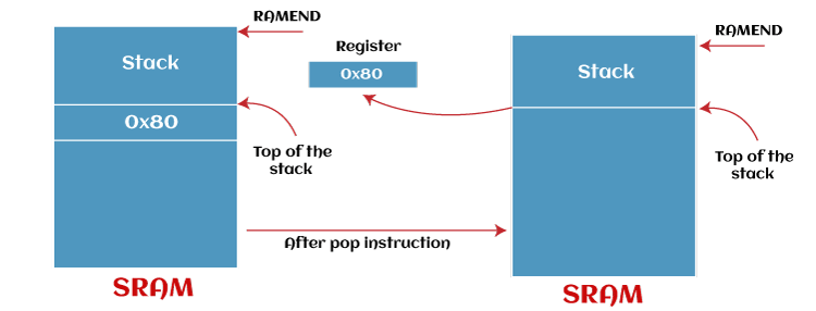
Example of PUSH and POP operation: In this example, we are going to load 30 into rax and then 45 into rex. The command to do this is described as follows: After executing the first push, the stack is going to have only a single value that is After executing the second push, the stack is going to have two values that are After executing the first POP, it will first pick up the value 45 and place it in the register rax. After that, the stack will have only one value that is After executing the second POP, it will pick up the value 17 and place it in the register rcx. After that, it will leave the stack clean. The last instruction, "ret" will not work perfectly if the stack is not clean. In this case, all the other instructions will work fine except the "ret". This instruction will jump onto the top of the stack no matter what data the stack contains on the top. Note: If the number of items that we pushed and the number of items that we popped are not the same, our program will be crashed. So we should be careful with our pushes and pops.When we try to push more than one resister into the stack, we should call the POP instruction in reverse order so that the values of their original registers will be restored, which is described as follows: As we can see that the above first, second, and third Push instructions store the content of r0, r1, and r3 respectively into the stack. In the Pop operation, the first Pop operation is performed on the r2 because it is entered in the last, and Pop operation is based on the LIFO operation. That's why we first Pop r2, and then r1 and r0. If we mistakenly call the POP instruction in the wrong order, in this case, the value will be restored into the wrong registers. So we should be careful while calling the POP, which is described as follows: As we can see that the calling of Pop instructions are not performed in the reverse order of what Push was called in. That's why the data of r20 and r21 are swapped in the result. But this feature will be great if we want to swap the two register's content without using the third register. Note: Registers must be pooped out from the stack in a reverse order that they were pushed so that they can restore their original values.Stack PointerThe stack pointer can be defined as a special register in the input/output memory, which is used to point the space that is allocated in SRAM. SP contains the 16-bit register, which also has the SPL and SPH. The SPH will not be required if the microcontroller contains a very small amount of SRAM. In this case, only SPL will be used. From the end of SRAM, the stack normally starts. When we store the data in a stack, it will grow from higher address values to lower address values. The top of the stack is always pointed with the help of a stack pointer. Initializing Stack pointers There are different amounts of RAM (random access memory) for the different AVRs. The address of the last RAM location can be specified with the help of RAMEND in the AVR assembler. So RAMEND can be loaded into the SP if we need to initialize the stack pointer to point to the last memory location. As we have learned above that, the stack pointer contains two registers that are SPH (high byte of stack pointer), SPL (low byte of stack pointer). So the high byte of RAMEND will be loaded into the SPH, and low byte of RAMEND will be loaded into the SPL. As we learn above that, the SP is in input/output memory. So we can use the out instruction to load the value into it. For the new AVRs, the last value of SRAM will be initialized with the help of stack point on power-up. For the older AVRs, it must be manually set up at the time of the beginning of any program. The example of this is described as follows: The include file is used to contain the constant RAMEND in the form of a last address in SRAM. A lot of microcontrollers contain the 16-bit address, which is divided into two 8-bit components with LOW function and HIGH function. These two functions will be loaded into a working register. The constant RAMEND can be less than 16 bits for some small microcontrollers. SPH will not be used in this case, and we will initialize only the SPL register. Note: Although, the SP is automatically initialized to the RAMEND on power-up with the help of a newer microcontroller. If we have the practice to initialize the stack pointer at the beginning of any program, it will be very good for us. In case of software reset, this practice will be very useful because it will protect the SP from beginning from some other location that is wrong.CALL instruction, RET instruction, and role of stackAt the time of execution of a CALL instruction, the address of instructions that are below the CALL instruction will be pushed onto the stack. The instructions, which are below the CALL instruction, will be loaded into the PC and will be executed when the subroutine execution is completed, and RET instruction is executed. |
 For Videos Join Our Youtube Channel: Join Now
Feedback
- Send your Feedback to [email protected]
Help Others, Please Share


