| |

Control system: CompensatorsThe compensators are derived from the word compensation. It means an adjustment in the arrangement of a structure to provide suitable performance. The working of feedback in the control system is essential. To improve the system's performance, the adjustment sometimes becomes an important part of obtaining the acceptable performance of feedback. It is because we often require changing or modifying the parameters of the system. A compensator in such cases helps in improving the control systems performance. The additional component called compensator is added to the structure of the control system while redesigning it. It is added to compensate for the deficient performance of the system. The types of a compensator can be hydraulic, electrical, mechanical, etc. Types of CompensatorThe compensators in the control system are classified as:
Lead compensatorThe lead compensator in a control system produces the output with a phase lead. Here, lead means ahead. It is a type of successor activity. Let's consider a lead compensator diagram. It is shown below: 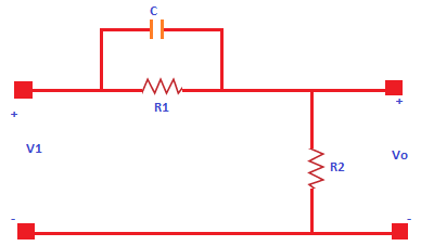
It consists of a two resistors, named as R1 and R2, and one capacitor C. The transfer function of a system is given by: Transfer function = Output/ Input The output of the lead compensator diagram is an RC circuit, and it depicts that the output is connected across the second branch. It has only one resistor, R2. So, the output of the circuit is R2. Vo(s) = R2 Let's find the input. The input will be the series or parallel combination of the elements (capacitor and resistors). The resistor R1 is connected in parallel with the capacitor C1. The equivalent parallel combination is further connected in series with the resistor R2. The parallel combination of two elements a and b in a circuit is a x b / a + b It will be: R1(1/Cs)/ (R1 + 1/Cs) The equivalent input is: Vi(s) = R2 + R1(1/Cs)/ (R1 + 1/Cs) Thus, the transfer function of the lag compensator will be: Transfer function = Output/ Input = Vo(s)/Vi(s) = R2 / {R2 + R1(1/Cs)/ (R1 + 1/Cs)} = R2(R1Cs + 1)/ {R1R2Cs + 1/(R1 + R2)) Dividing and multiplying the above transfer function with R1 + R2, we get: R2/(R1 + R2) (R1Cs + 1)/{R1R2Cs/(R1 + R2) + 1} Let, T = R1C A = R2/ (R1 + R2) So, the above transfer function can be written as: Vo(s)/Vi(s) = A (Ts + 1)/ (TAs + 1) We know that the numerator of the transfer function determines the zeroes of the system, and the denominator determines the poles. Thus, from the given transfer function, we can conclude that: Pole = -1/AT Zero = - 1/T The maximum angle that a lead compensator can introduce in the system is given by: Phase angle = sin-1(1 - A / 1 + A) It can also be written as 90 - 2tan-1(A)1/2 The maximum frequency at the given maximum angle is: 1/T(A)1/2 Lag compensatorThe lag compensator in a control system produces the output with a phase lag. Here, lag means behind or delay. Let's consider a lag compensator diagram. It is shown below: 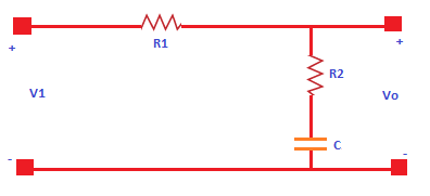
It consists of a two resistors, named as R1 and R2, and one capacitor C. The transfer function of a system is given by: Transfer function = Output/ Input The output of the lag compensator diagram is an RC circuit. It clearly depicts that the output is connected across the second branch. It has one resistor R2 and a capacitor C connected in series. So, the output of the circuit is: Vo(s) = R2 + 1/Cs Let's find the input. The input will be the series or parallel combination of the elements (capacitor and resistors). The resistor R1 is connected in series with the series combination of R2 and C. We will first calculate the series combination and further it with the other series combination. The series combination of two elements a and b in a circuit is a + b It will be: R2 + 1/Cs The equivalent input is: Vi(s) = (R1 + R2 + 1/Cs) Thus, the transfer function of the lag compensator will be: Transfer function = Output/ Input = Vo(s)/Vi(s) = R2 + 1/Cs/ (R1 + R2 + 1/Cs) = CsR2 + 1/(Cs(R1 + R2) + 1) = Ts + 1/ (BTs + 1) Let, T = CR2 B = (R1 + R2) So, the above transfer function can be written as: Vo(s)/Vi(s) = 1 + Ts/ 1 + BTs We know that the numerator of the transfer function determines the zeroes of the system and the denominator determines the poles. Thus, from the given transfer function, we can conclude that: Pole = -1/BT Zero = - 1/T The maximum angle that a lead compensator can introduce in the system is given by: Phase angle = sin-1(1 - B / 1 + B) The maximum frequency at the given maximum angle is: 1/T(B)1/2 Before beginning with the differences, let's discuss the GCP (Gain Crossover Point) in compensators. GCPThe gain crossover point in compensators is a frequency point at which the open-loop gain first reaches the value of 1. We can also say that the GCP is a point at which the open loop gain reaches the 0-db axis. It is because the value of gain 1 in terms of logarithmic is 0 (log 1 = 0). The differences between the phase lead and phase lag compensators are as follows:
Lag-lead compensatorAs the name implies, the lag-lead compensator is combination of lag and lead compensator. The lag compensator in a control system produces the output with a phase lag. The lead compensator in a control system produces the output with a phase lead. Thus, the lag-lead compensator produces the output with phase lg at one frequency region and phase lead at the other frequency region. Let's consider a lag-lead compensator diagram. It is shown below: 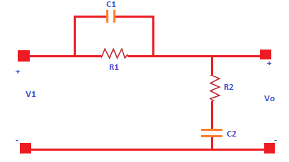
It consists of a two resistors, named as R1 and R2, and two capacitors C1 and C2. The transfer function of a system is given by: Transfer function = Output/ Input The output of the lag compensator diagram is an RC circuit, and it depicts that the output is connected across the second branch. It has one resistor, R2 and a capacitor, C2, connected in series. So, the output of the circuit is: Vo(s) = R2 + 1/C2s Let's find the input. The input will be the series or parallel combination of the elements (capacitor and resistors). The resistor R1 is connected in parallel with the capacitor C1. The second branch has the series combination of the resistor R2 and C2. We will first calculate the series combination of C2 and R2, the parallel combination of R1 and C1, and further both as the series combination. The series combination of two elements a and b in a circuit is a + b It will be: R2 + 1/C2s The parallel combination will be: R1 x 1/C1s/(R1 + 1/C1s) The equivalent input will now be the series combination of the above listed combinations, which is given by: Vi(s) = R2 + 1/C2s + R1 x 1/C1s/(R1 + 1/C1s) Vi(s) = {(R2 + 1/C2s) (R1 + 1/C1s) + R1 x 1/C1s}/ ((R1 + 1/C1s) Thus, the transfer function of the lag compensator will be: Transfer function = Output/ Input = Vo(s)/Vi(s) =( R2 + 1/C2s)/ {(R2 + 1/C2s) (R1 + 1/C1s) + R1 x 1/C1s}/ ((R1 + 1/C1s) = (R2 + 1/C2s) (R1 + 1/C1s) /R1R2C1C2s2 + (R1C1 + R2C2 + R1C2)s + 1 Let, AT1 = R1C1 BT2 = R2C2 T1T2 = R1R2C1C2, if AB = 1 Vo(s)/Vi(s) = (1 + AT1s) (1 + BT2s)/ (1 + T1s) (1 + T2s) So, the above transfer function can be written as: Vo(s)/Vi(s) = (1 + AT1s) (1 + BT2s)/ (1 + T1s) (1 + T2s) Advantages of the lag-lead compensator The advantages of lag-lead compensator are as follows:
Applications of the lag-lead compensator The applications of lag-lead compensator are as follows:
ExamplesLet's discuss some examples based on the compensators. The examples will be Multiple Choice Questions, as it helps us in the competitive exams. Example 1: Find the phase shift provided by the lead compensator with the transfer function given by: Transfer function = (1 + 6s) / (1 + 2s).
Answer: (a) 30 degrees Explanation: The transfer function of the lead compensator is in the form: = s + 1/T divided by s + 1/AT Comparing, (1 + 6s) / (1 + 2s) or with (s + 1/T) / (s + 1/AT), we get: A = 1/3 The maximum phase shift of the lead compensator is given by: Phase angle = sin-1(1 - A / 1 + A) = sin-1(1 - 1/3 / 1 + 1/3) = sin-1(2/4) = sin-1(1/2) = 30 degrees Example 2: The transfer function given below represents which type of compensator. Transfer function = 1 + 0.5s/ 1 + s
Answer: (b) Lag compensator Explanation: The transfer function of the lag compensator is in the form Vo(s)/Vi(s) = 1 + Ts/ 1 + BTs. After comparing, we can find out the given transfer function is a type of lag compensators. Example 3: The phase-lead compensator for a gain constant K,
Answer: (d) All of the above Explanation: The phase margin increases due to the addition of phase angle near the gain crossover point. It also increases the gain crossover frequency due to the increase in the gain at high frequencies. It also reduces the slope magnitude curve in the entire range. Example 4: A lead compensator used for a closed loop system controller has the following transfer function K(1 + s/a)/(1 + s/b). The condition for such as lead compensator is given by:
Answer: (a) a < b Explanation: The phase angle for the phase lead compensator is generally positive. It is given by: Tan-1w/a - tan-1w/b For the angle to be positive, Tan-1w/a should be greater than the tan-1w/b. Hence, a < b
Next TopicState Space Model
|
 For Videos Join Our Youtube Channel: Join Now
Feedback
- Send your Feedback to [email protected]
Help Others, Please Share


