| |

Control system: Examples with ExplanationHere, we will discuss the examples related to the block diagram reduction, signal flow graph, mason's gain formula, and basic concepts of the control system. The examples will be MCQ based because that will help in the competitive exams as well. Example 1:Find the transfer function of the given block diagram. 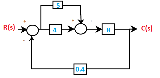
Answer: (d) 2.416 Solution: In the given block diagram, R(s) is the input and C(s) is the output. The transfer function of the system will be the ratio of the output and the input. It is given by: C(s)/R(s) Let's begin with the steps to solve the transfer function of the system. Step 1: We will first combine the two blocks in parallel using the rule that the value of the two blocks in parallel is added, forming an equivalent block. It is shown below: 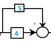
4 + 5 = 9 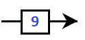
After solving, the block diagram will now appear as: 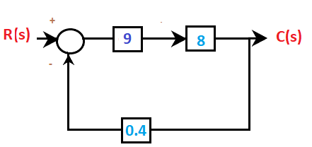
Step 2: Now, we will combine blocks in series using the rule that the value of the two blocks in cascade is multiplied forming an equivalent block. It is shown below: 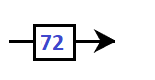
9x8 = 72 The block diagram after the second step will appear as: 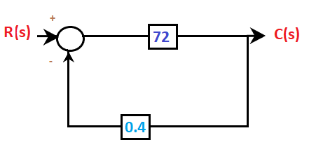
We are left with a close loop. The close loop transfer function is given by: C(s)/R(s) = 72/1 + 72x 0.4 = 72/29.8 = 2.416 C(s)/R(s) = 2.416 Example 2:The transfer function of a linear system is given by:
Answer: (c) Ratio of the Laplace transforms of the output Vo(s) and the input Vi(s) of the system. Solution: For a given block diagram or characteristic equation, the transfer function of a linear system is always expressed in terms of Laplace. It is calculated as the ratio of the Laplace transform of the system's input and output. For example, Vo = (1 + t2) Vi The transfer function of the above equation can be calculated by first taking the Laplace, which is given by: Vo (s) = (1/s + 2/s3) Vi(s) Vo (s)/ Vi(s) = (1/s + 2/s3) Thus, the transfer function is (1/s + 2/s3). It is obtained after assuming all the initial conditions as zeroes. Example 3:Find the transfer function of the given block diagram. 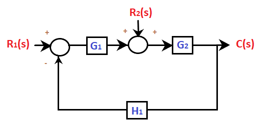
Answer: (b) C(s) = G1G2 R1(s) / (1 + G1G2H1) + G2R2(s) /(1 + G1G2H1) Solution: The above question is of system with multiple inputs. Let's consider some steps that may help to solve the problems with multiple inputs.
In order to solve the above problem, follow the below steps: Step 1: In the given figure, there are two inputs R1 and R2. Let's first set R1 =0. The block diagram thus arranged will appear as: 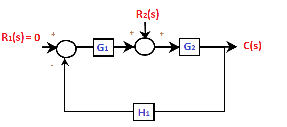
The resulted block diagram will now appear as: 
The transfer function will be: C2(s)/R2(s) = G2/(1 + G1G2H1) C2(s) = G2R2(s) /(1 + G1G2H1) ... (1) Step 2: Now assume R2 = 0 The block diagram thus arranged will appear as: 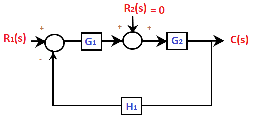
The resulted block diagram will now appear as: 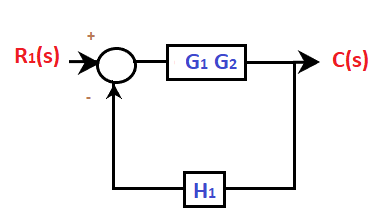
The transfer function will be: C1(s)/R1(s) = G1G2/(1 + G1G2H1) C1(s) = G1G2 R1(s) / (1 + G1G2H1) ... (2) Now, adding both the equations, we will get the desired transfer function. It is given by: C(s) = C1(s) + C2(s) C(s) = G1G2 R1(s) / (1 + G1G2H1) + G2R2(s) /(1 + G1G2H1) C(s) = (G1G2 R1(s) + G2R2(s))/( 1 + G1G2H1) Example 4:The type of system denotes the number of:
Answer: (b) Poles at the origin Solution: The type of system usually denotes the number of poles at the origin. If there are two poles at the origin, it means that the system is of type 2. Type 1 signifies the open loop transfer function and has 1 pole at the origin. Similarly, we can say that if the system has no pole at the origin, it is categorized under Type-0 systems. Example 5:In the given signal flow graph, y/x equals to: 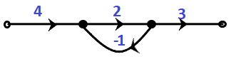
Answer: (b) 8 Solution: There is only one loop present in the signal flow graph. The gain of the loop is given by: 2/( 1 + 2(1)) = 2/3 All the other branches are connected in cascade or series. Hence, the equivalent result will be the product of all the values at the three nodes. y/x = 4 x 2/3 x 3 = 8 Example 6:The purpose of the signal flow graph is to find the:
Answer: (a) transfer function of the system Solution: The signal flow graph in control system is used to find the transfer function of the system, such as Mason's gain formula. It was specially designed to find the transfer function of a signal flow graph, which includes non-touching loops and forward-path gain. Example 7:Find the transfer function of the given signal flow graph.
Answer: (c) 44/23 Solution: We know that the transfer function of the signal flow graph is generally calculated using the mason's gain formula, which is given by: 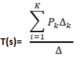
Where, Pk is the forward path gain ∆ It is the loop gain. The loop gain is calculated as: 1 - Summation of all loop gain + Summation of gain product of two non-touching loops - Summation of gain product of three non-touching loops ∆k It is calculated by eliminating all loops touching the forward path Pk. Let's discuss the solution of given signal flow graph. As per the given diagram, there are two forward paths. P1 = 5 P2 = 1x2x3x4 = 24 There are four individual closed loops. L1 = -5 L2 = -2 L3 = -3 L4 = -4 There are only two non-touching loops, namely L2 and L4. The product of these two loops is: (-2) x (-4) = 8 Thus, the transfer function of the given signal flow graph is: = 5 (1 + 3) + 24/ 1 + (5 + 2 + 3 + 4) + 8 = 44/23 Example 8:Find the initial value f(t) of the transfer function F(s) = 4 /s2+2s + 5, where F(s) is the Laplace transform of the function f(t).
Answer: (c) 0 Solution: The initial value of the transfer function is given by: 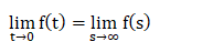
So, we will put, s = infinity in the given transfer function F(s) = 4 /s2+2s + 5. We get, F(s) = 0 Example 9:Which of the following statement is incorrect?
Answer: (c) The transfer function is represented along the branch in the block diagram Solution: Let's discuss each of the four statements in detail.
Example: 10The transfer function of the given block diagram is: 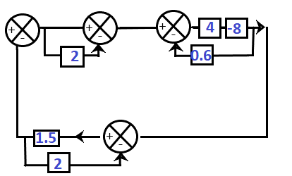
Answer: (a) -1.714 Solution: Here, the given block diagram has three loops. So, we will first solve these three loops. The steps 1, 2, and 3, are marked below: 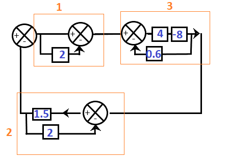
Step 1: It has one block and a unity line in parallel. The unity line, when connected with a block in parallel, is considered as 1. As per the rule, the equivalent value of the blocks in parallel is added. So, = 2 + 1 = 3 Step 2: It contains two blocks, where one block is present in the feedback path. So, we will use the transfer function formula where G(s) and H(s) are 1.5 and 1 respectively. = 1.5/1 + 1.5x2 = 1.5/4 Step 3: The first two blocks in the cascade will be multiplied. = 5 x -8 = -40 It has a feedback path of value 0.6. So, we will use the transfer function formula given by: G(s)/1 - G(s)H(s) Where, G(s) and H(s) are -40 and 0.6 respectively. The resultant value of the block will be: -40/ 1 + (40)(0.6) = -40/25 The resulted block diagram will now appear as: 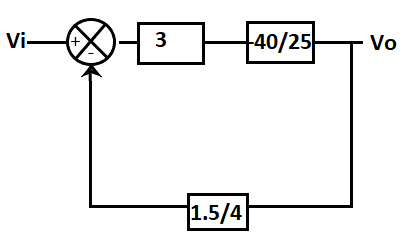
Step 4: The transfer function of the block diagram will be: Vo(s)/Vi(s) = -(40/25) x3/ {1 + 40/25 x 3 x 1.5/4) = (-120/25)/ 2.8 = -120/70 = -1.714
Next TopicTime response Analysis
|
 For Videos Join Our Youtube Channel: Join Now
Feedback
- Send your Feedback to [email protected]
Help Others, Please Share


