| |

Dotted line command in SolidWorksText in LineWith drawings, you may indicate the color, thickness, and style of:
Layers or the Line Color tool can be used to determine the color for notes and other markings. There are two options for setting the line formats:
The line format adheres to the Layer settings when additional sketch entities are added to a drawing. If there isn't a layer active, the system settings govern the line format. The line format tool settings take precedence over layer specifications and system settings for new sketch entities and annotations. Component Line Font is another tool for configuring edge attributes for assembly components in designs. Formatting toolsThe following formats can be modified via the tools on the Line Format toolbar. Layer Specifications: Choose a layer for new entities, transfer existing entities into layers, and set the layer's attributes (Color, Thickness, and Style). Line Shade: To change the default settings, either picks Default or a color from the palette. Under Settings, Colors, Color scheme settings, you may choose the default colors for drawings and measurements. Using the Color Display Mode tool, you may switch between the desired color and the system default colors (below). 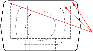
Size of the lines.Choose:
The name of the thickness is shown in the status bar when you move the pointer over the menu. In Document Properties - Line Thickness, corresponding line weights for printing are specified. 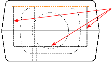
Line Format: Choose Default or a style from the menu. Also, you may design your own line styles and use them on the edges of designs. 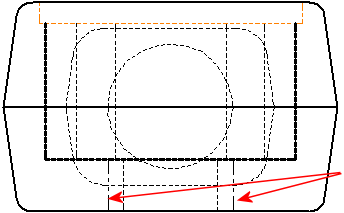
Edges, Show/Hide: The edges of a drawing are hidden and shown. Display Mode for Color: Toggle between aesthetic colors (colors selected in layers or with Line Color) and the system status colors by using this tool (fully defined, under defined, and so on). Dangling dimensions and sketch endings are always colored according to the system status. In the present and future drawings, the following format for new sketch entities is specified:
Unless you choose a new format, the entities you add to the drawing utilise the provided forms. To modify an existing edge or sketch entity's format:
The chosen entities are given the new format. To restore the font's default settings or the edge color, thickness, or size: Reset line font may be found by right clicking an edge. Modifying line fonts for components in drawings in SOLIDWORKS It may be desired to represent assembly components or certain edges of a model using distinct line styles, thicknesses, or colors when designing drawing views in SOLIDWORKS. Perhaps you want to call attention to a certain aspect of the design or make the graphics simpler to read. This is a technique you may use for whatever reason. Let's begin with a part of an assembly. You may choose numerous components by holding down the Ctrl key as you right-click each one you want to change in the drawing view in the graphics area. You can also make your selections from the Feature Manager design tree. I've chosen the army knife's basic part for this illustration. 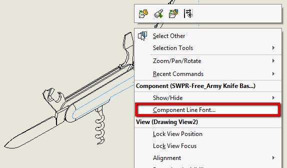
The Component Line Font dialogue box will appear as a result. The component display would adhere to the Document Properties of the template accessible in Tools > Options > Document Properties if the box labelled "Use document defaults" is ticked. You may change the Line style and thickness for various edge kinds, such as visible, concealed, and tangent edges, by unchecking this box. 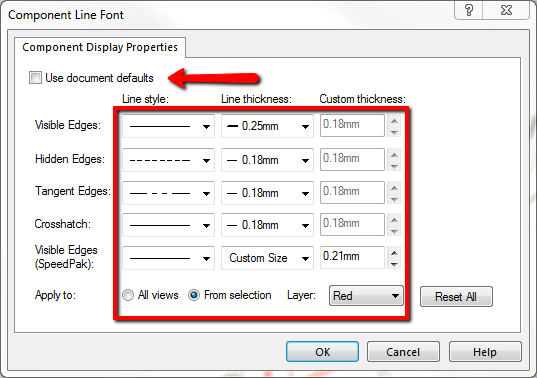
This adjustment can be made to all views or only the chosen view. Also, you may assign it to the layer from this menu if you have already established one. The color may be altered with this. I positioned it on the "Red" layer and thickened the base's visible borders in the chosen view. The results of the tweaks I made to several of the tools are shown below. 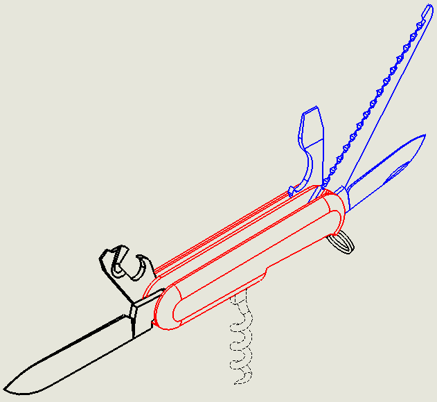
If you only want to change a few edges or lines, you may access Line Color, Thickness, and Style from the Context Toolbar by selecting the entities you wish to change. By selecting View > Toolbars > Line Format, you may make the Line Format toolbar available if you plan to make a lot of modifications. Not only will the tools be available to you, but also layers. 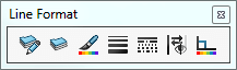
Next TopicMirror command in Solid Works
|
 For Videos Join Our Youtube Channel: Join Now
Feedback
- Send your Feedback to [email protected]
Help Others, Please Share


