| |

DSBSC (Double Sideband Suppress Carrier)DSB is a type of Amplitude Modulation. It has two sidebands on both sides of the carrier frequency. The terms suppress means to remove. The suppressed carrier means to remove the carrier. Thus, DSB SC is a transmission that does not involve the carrier component at the output of the modulator. We can define the DSBSC transmission as: 'The transmission that produces two sidebands symmetric above and below the carrier frequency with the carrier reduced to the lowest possible level of frequency is known as Double Sideband Suppress Carrier transmission.' The power is distributed in its two sidebands because the absence of carrier results in no carrier power. Thus, the cover of DSBSC is more as compared to the Amplitude Modulation. However, the carrier signal is essential to recover the signal required during the demodulation. Here, we will discuss DSBSC modulator, DSBSC demodulator process, power, efficiency, advantages, disadvantages, and a numerical example. Let's start. Suppose the spectral density of the non-periodic signal is of finite energy, as shown below: 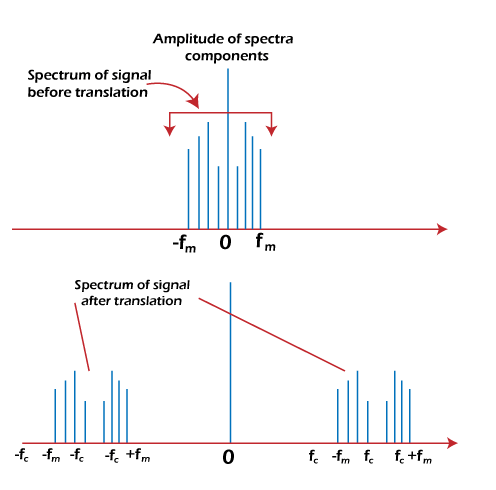
The signal is represented in the frequency domain of its Fourier transform. Suppose the signal is band-limited from 0 to Fm. Its Fourier transform will be symmetric about the axis. We know that the baseband signal is the unmodulated one, and the original one is also unmodulated. On this basis, we can also name the original signal as the baseband signal. Thus, the spectral range is called the baseband frequency range. The spectral density of the signal is multiplied by the carrier signal cosωct. The superposition of the message signal on the high-frequency carrier signal is called modulation and the process of multiplying the signal with an auxiliary sinusoidal signal is called mixing. It is given by: Function 1/2[m(t)cosωct] = [M(ω + ωc) + M(ω - ωc)] 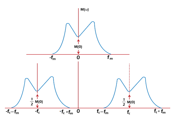
The part of the signal above the auxiliary frequency range is known as the upper-sideband from Fc to Fc + Fm. The part of the signal below the auxiliary frequency range is known as the lower-sideband from Fc - Fm to Fc. The upper-sideband is represented by the carrier frequency and message frequency sum, while the lower sideband represents the difference. The process of Double Sideband Suppress Carrier modulation can be an advantage or disadvantage depending on different applications. It is called DSB because both the upper and lower sidebands are transmitted with the same message contents. It is called SC because the carrier signal is not sent separately. DSB SC ModulatorA multiplier is a device that produces the output. It is the multiplication of the two input signals. For the product, there should be atleast two input signals. For example, A modulation device has two input signals, a message signal m(t) and the carrier signal cosωct. The baseband signal frequency is much less than the frequencies of the carrier signal Fc. Fc = ωc/2π Let's consider another example. If the baseband frequency is 1k Hz and the carrier signal frequency is 1M Hz, the sidebands will extend from the range as follows: (1M - 1k) Hz to (1M + 1k) Hz (106 - 103) Hz to (106 + 103) Hz (1000000 - 1000) to (1000000 + 1000) Hz 999000 Hz to 1001000 Hz The baseband signal can be easily removed from the signal using the filter. Thus, the output is called a double sideband amplitude modulated signal. We can also suppress the carrier if we require the product signal alone. It can be done by adding a carrier of equal frequency with the opposite phase. In such cases, only the sideband remains. Balance ModulatorThe balanced modulator comprises of two amplitude modulators and one adder. The modulated signal from the output of the two modulators is added with consequent carrier suppression. A filter in the balanced modulator can also eliminate the baseband signal. The diagram of the balanced modulator is shown below: 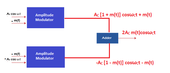
Non-linear ModulatorIt has three adders, two non-linear devices, and a band pass filter. The diagram of the non-linear modulator is shown below: 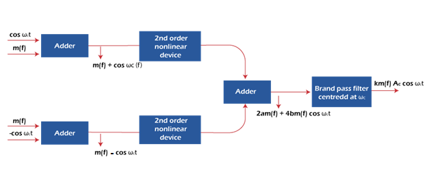
The carrier on both the inputs of the adder is of opposite phase, i.e., cosωct and -cosωct. The upper block input is: V1(t) = m(t) + cosωCt The lower block input is: V2(t) = m(t) - cosωCt The output of the summer will be: S(t) = a[v1(t) - v2(t)] + b[v12(t) - v22(t)] Substituting the values of v1(t) and v2(t) and after solving, we get: S(t) = 2am(t) + 4bm(t)cosωct The first term is the baseband signal and the second term is the desired DSB-SC signal. The summation block is centered on the cut-off frequency ωc + ωm. The non-linear modulator requires a band pass filter to remove the message signal from the output. DSB SC DemodulatorDemodulation is the process opposite to modulation. The function of the demodulator is to recover the signal at the receiving end. We have already seen how the signal is multiplied by the carrier signal. The baseband signal is recovered from the output of the multiplier. Here, we will discuss the two methods to recover the baseband signal. The first method is the coherent method that requires a carrier signal at the receiving end to recover the signal. The carrier signal is in coherence with the carrier at the transmitter side. The other non-coherent method does not require any coherent carrier at the receiver. It is complex than the first method. Coherent detectionHere, the signal is recovered from the modulated signal by a reverse frequency translation process. The translated signal is multiplied by the carrier signal cosωct. It is because the recovery depends on the carrier. There is no carrier during the modulation. Hence, it is generated at the receiving end for successful recovery. The spectral range produced after the multiplication is the same baseband range. It is given by: [m(t) cosωCt] cosωCt = m(t) cosωC2t = m(t) (1/2 + 1/2cos2ωCt) = m(t)/2 + m(t)/2 cos2ωCt A signal addition to the baseband signal is also produced whose spectral range extends from 2Fc - Fm to 2Fc + Fm. The block diagram showing the frequency representation at the input and output is shown below: 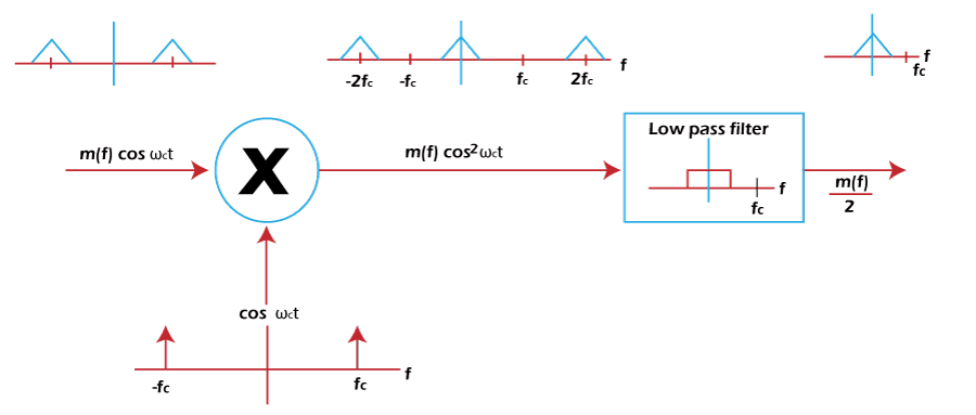
Disadvantages of coherent detection The coherent detection method of signal recovery suffers from two inconveniences.
A phase shifter can be used to correct the phase variation. Some distortion in every physical system is tolerable to some extent. Square synchronizerWe have discussed the requirements of a synchronous auxiliary signal. It can be generated with the help of a synchronizer. The square synchronizer uses a complicated method to provide a synchronous auxiliary signal at the receiver. To illustrate, we assume a carrier signal cosωct and baseband signal cosωmt. The received signal will be: S(t) = A cosωct cosωmt Where, A is the amplitude constant The output of the squaring circuit will be the square of the input signal. Squaring both sides, we get: S(t)2 = A2 cosωc2t cosωm2t S(t)2 = A2 (1/2 + cos2ωct/2) (1/2 + cos2ωmt/2) We can use the PLL (Phase Lock Loop) to track the carrier frequency. The frequency division can be further accomplished by using a bistable multivibrator. The output of the divider will act as a demodulator and help recover the baseband signal cosωmt. Power calculation of DSBSCThe power in DSBSC is distributed between the two sidebands. So, the total power is the sum of upper sideband power and lower sideband power. It is given by: Pt = Pu + Pl Upper Sideband powerPower formula = Square of RMS voltage/R P = Vrms2/R Where, RMS voltage = Maximum voltage / sqrt 2 Vrms = Vm / (2)1/2 We know, Vm = AC Am/2 Substituting the value of maximum voltage in RMS voltage, we get: Vrms = AC Am / 2(2)1/2 P = (AC Am / 2(2)1/2)2/R Pu = AC 2Am2/8R Lower Sideband Power It is same as the upper sideband power Pl = AC 2Am2/8R Total power = AC 2Am2/8R + AC 2Am2/8R Total power = 2 AC 2Am2/8R Total power = AC 2Am2/4R Thus, the power of the Double Sideband Suppress Carrier is AC 2Am2/4R. Advantages of DSBThe advantages of DSB are as follows:
Disadvantages of DSBSCThe disadvantages of DSB are as follows:
Applications of DSBSCThere are various applications of DSBSC. Let's discuss some of the most applications of Double Sideband Modulation.
EfficiencyThe basic equation of Amplitude Modulation is given by: V(t) = AC [1 + m(t)] cosωCt V(t) = AC cosωCt + ACm(t)cosωCt The first term represents the power required to transmit the carrier Ac2/2 and the second term represents the power in the sidebands. The total power is the sum of the power transmitted in the carrier and sidebands. The carrier is commonly used in the demodulation process. There is no use of the carrier in the modulation process and neither carries any information. The useful power is transmitted in the sidebands. Hence, sideband power is of great importance. The efficiency of Amplitude Modulation is defined as the ratio of sideband power to the total power. Efficiency = Ps/Pt The total power is the sum of sideband power and the carrier power. Pt = Ps + Pc Thus, we can also define the efficiency as: Efficiency = Ps/ Ps + Pc We know, V(t) = AC cosωCt + ACm(t)cosωCt The message signal m(t) can be represented as: M(t) = Am cosωmt Putting the value of m(t) in the above equation, we get: V(t) = AC cosωCt + AC Am cosωmt cosωCt V(t) = AC cosωCt + AC Am/2 (cos (ωC + ωm) + cos (ωC - ωm)) Thus, the useful sideband power is: Ps = 1/2 [(AC Am)2/2 + [(AC Am)2/2] Ps =0.5 (AC Am)2 Substituting the value of sideband power in the efficiency formula, we get: Efficiency = 0.5 (AC Am)2/(Ac2 +0.5 (AC Am)2) Efficiency = Am2/(2 + Am2) Thus, the efficiency of the DSB is Am2/(2 + Am2) Where, Am is the modulation index of the signal In DSBSC, the efficiency is 50% due to the absence of carrier. The maximum efficiency of 100% can be achieved using the SSBSC (Single Side Modulation Suppress Carrier). Using the coherent detection method, we can recover the signal for any value of modulation index. Numerical ExampleLet's discuss a numerical based on DSBC. Example: Find the transmission power efficiency of the modulated signal when the modulation index is 0.5, 0.8 and 0.3. Solution: The formula to calculate the transmission power efficiency of the modulated signal is given by: Efficiency % = A2/(A2 + 2) x 100 Where, A is the modulation index For A = 0.5 Efficiency = 0.52/0.52 + 2 x 100 = 0.25/2.25 x 100 = 1/9 x 100 = 11.11% For A = 0.8 Efficiency = 0.82/0.82 + 2 x 100 = 0.64/2.64 x 100 = 24.24% For A = 0.3 Efficiency = 0.32/0.32 + 2 x 100 = 0.09/2.09 x 100 = 4.3%
Next TopicDSBC
|
 For Videos Join Our Youtube Channel: Join Now
Feedback
- Send your Feedback to [email protected]
Help Others, Please Share


