| |

Embedded System I/O ProgrammingIn 8051 Microcontroller, I/O operations are performed by using four ports and 40 pins. I/O operation port uses 32 pins with each port has 8 pins. The remaining 8-pins are used for providing Let's see the 40-Pin Plastic Dual Inline Package (PDIP) integrated circuit of microcontroller: 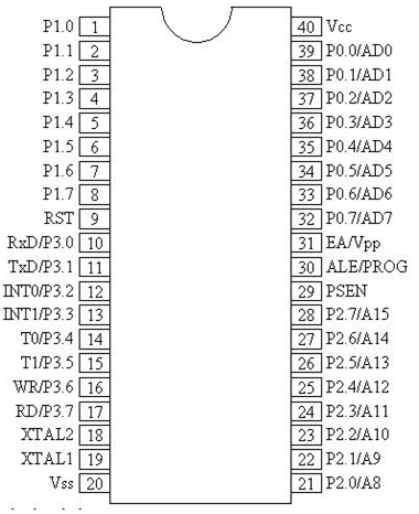
Note - In DIP structure of microcontroller we can recognize the first and last pin by using the cut present at middle of IC this cut is called as Notch of microcontroller. The first pin is present at left side of notch and last pin is present at right side of notch. I/O Ports and their Functions:In microcontroller there are four Input/output ports P0, P1, P2, and P3, each port is 8-bit port having 8 pins each. During RESET, all the ports are used as input ports. When the port gets first 0, then it becomes an output port. For reconfigure it as an input, the high signal (1) must be sent to a port. Port 0 (Pin No 32 - Pin No 39): Port 0 contains 8 pins. It can be used as input or output. In general we connect P0 with 10K-ohm pull-up resistors for using it as an input or output port being an open drain. It is also referred as AD0-AD7, which allowing it to be used as both address and data transfer port. When we want to excess the external ROM, then P0 is used as both Data and Address Bus. Address Latch Enable (ALE) Pin no 31 indicates if PO is used as address or data. When ALE=0 then it provides data D0-D7. When ALE=1 then it provides address A0-A7. Let's see the structure of port 0 with externally connected pull up resistor: 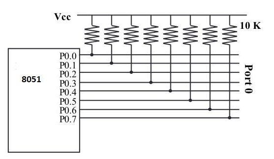
Let's see an assembly language code for making the Port 0 to be worked as an input:- Port 1 (Pin No 1-Pin No 8): It is also an 8-bit Port and can be worked as either input or output. It doesn't require external connected pull-up resistors because they are already present internally. Upon reset, Port 1 worked as an input port. If port 1 is configured as an output port, then to use port 1 as input port again, we write 1 to all bits of port 1 as shown in the below code:- Port 2 (Pin No 21-Pin No 28): Port 2 uses a total of 8 pins and it can also be used as input and output operation. Same as Port 1, P2 also not require external pull- up resistors. Port 2 can be used along with P0 to provide 16-bit address for an external memory. Therefore it is designated as (A0-A7), as shown in pin diagram. If Port 2 is configured as an output port, then for using it as an input port again we write 1 to all bits of port 2 as shown in the below code:- Port 3 (Pin No 10-Pin No 17): Port 3 is also of 8 bits and it can be used as Input/output. This port provides some important signals. P3.1 and P3.0 are RxD (Receiver) and TxD (Transmitter) respectively and it is collectively used for serial communication. P3.3 and P3.2 pins are used as external interrupts. P3.5 and P3.4 are used as timers T1 and T0 respectively. P3.6 and P3.7 are Write (WR) and Read (RD) pins. Let's see the Port 3 table showing an individual pin function:
I/O Ports and Bit Addressability:It is a mostly used feature of 8051 while writing code for 8051. Sometimes there is a need to use only 1 or 2 bits of the port instead of using entire 8-bits. 8051 microcontroller provides the feature to use each bit of the ports. While using a port in a single-bit manner, we provide the syntax "SETB X.Y", where X is the port number varies from 0 to 3, and Y is a bit number varies from 0 to 7. For example: - "SETB P1.3" sets high bit 3 of port 1. Let's see an assembly code for toggling the bit of P1.5 continuously: Single Bit Instruction:
Next TopicAddressing Modes
|
 For Videos Join Our Youtube Channel: Join Now
Feedback
- Send your Feedback to [email protected]
Help Others, Please Share


