| |

EncodersThe combinational circuits that change the binary information into N output lines are known as Encoders. The binary information is passed in the form of 2N input lines. The output lines define the N-bit code for the binary information. In simple words, the Encoder performs the reverse operation of the Decoder. At a time, only one input line is activated for simplicity. The produced N-bit output code is equivalent to the binary information. 
There are various types of encoders which are as follows: 4 to 2 line Encoder:In 4 to 2 line encoder, there are total of four inputs, i.e., Y0, Y1, Y2, and Y3, and two outputs, i.e., A0 and A1. In 4-input lines, one input-line is set to true at a time to get the respective binary code in the output side. Below are the block diagram and the truth table of the 4 to 2 line encoder. Block Diagram:
Truth Table: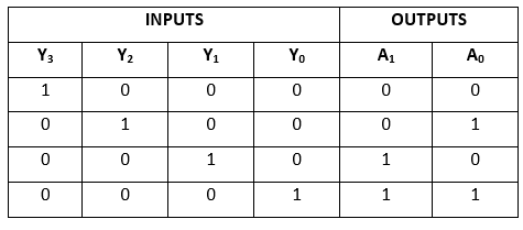
The logical expression of the term A0 and A1 is as follows: A1=Y3+Y2 Logical circuit of the above expressions is given below: 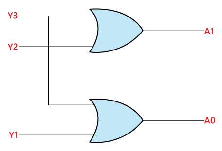
8 to 3 line Encoder:The 8 to 3 line Encoder is also known as Octal to Binary Encoder. In 8 to 3 line encoder, there is a total of eight inputs, i.e., Y0, Y1, Y2, Y3, Y4, Y5, Y6, and Y7 and three outputs, i.e., A0, A1, and A2. In 8-input lines, one input-line is set to true at a time to get the respective binary code in the output side. Below are the block diagram and the truth table of the 8 to 3 line encoder. Block Diagram:
Truth Table: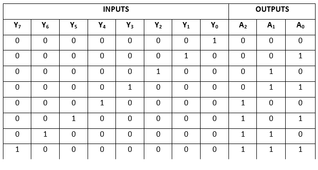
The logical expression of the term A0, A1, and A2 are as follows: A2=Y4+Y5+Y6+Y7 Logical circuit of the above expressions is given below: 
Decimal to BCD EncoderThe Octal to Binary Encoder is also known as 10 to 4 line Encoder. In 10 to 4 line encoder, there are total of ten inputs, i.e., Y0, Y1, Y2, Y3, Y4, Y5, Y6, Y7, Y8, and Y9 and four outputs, i.e., A0, A1, A2, and A3. In 10-input lines, one input-line is set to true at a time to get the respective BCD code in the output side. The block diagram and the truth table of the decimal to BCD encoder are given below. Block Diagram:
Truth Table: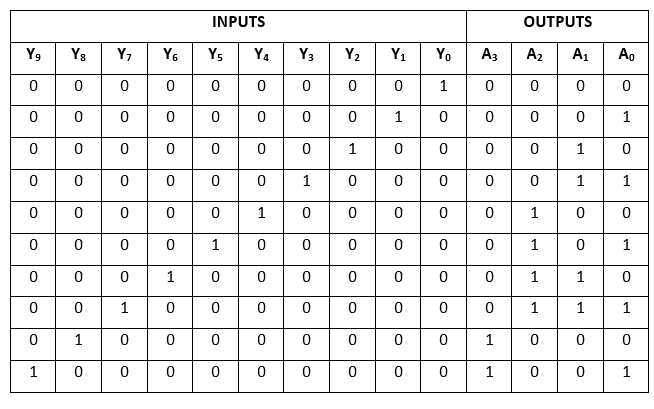
The logical expression of the term A0, A1, A2, and A3 is as follows: A3 = Y9 + Y8 Logical circuit of the above expressions is given below: 
Priority Encoder:4 to 2 line Priority Encoder:In this priority encoder, there are total of 4 inputs, i.e., Y0, Y1, Y2, and Y3, and two outputs, i.e., A0 and A1. The Y3 has high and Y0 has low priority inputs. When more than one input is '1' at the same time, the output will be the (binary) code corresponding to the higher priority input. Below is the truth table of the 4 to 2 line priority encoder. Truth Table: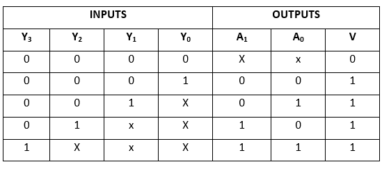
The logical expression of the term A0 and A1 can be found using K-map as: 
A1=Y3+Y2 Logical circuit of the above expressions is given below: 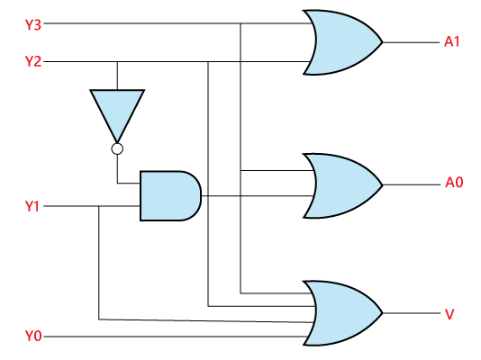
Uses of Encoders:
Next TopicMultiplexer
|
 For Videos Join Our Youtube Channel: Join Now
Feedback
- Send your Feedback to [email protected]
Help Others, Please Share


