| |

Execution, Stages and Throughput in PipelineWe are able to improve the performance of CPU with the help of two ways, which are described as follows:
Since there is a high cost of the faster circuit, and the speed of hardware is also limited. Because of these drawbacks, the 2nd option is good for us. PipeliningPipelining can be described as a technique in which multiple instructions are overlapped at the time of execution. There are five stages in the pipeline, and all these stages are connected with each other so that they can form a pipe-like structure. In the pipeline, there are two ends in which one end is used to enter the instruction, and the second end is used to exit it. Because of the pipeline, the overall instruction throughput is increased. Each segment of the pipeline system has the input register followed by a combinational circuit. The data is contained with the help of a register, and operations on that data are performed with the help of this combinational circuit. The result of a combinational circuit will be applied to the input register of next segment. 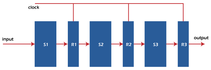
The pipeline system also works as a setup of the modern-day assembly lines in various types of factories. For example: suppose there is a car manufacturing industry in which a large number of assembly lines are set up, and a certain task is performed by robotic arms at each point. After that, the car will be moved ahead to the next arm. In the process of pipelining, the hardware elements of CPU will be arranged in a way that the overall performance can be increased. In the process of a pipeline, more than one instruction can be executed simultaneously. For example: Here, we will learn the concept of pipeline operation with the help of a real-life example. In this example, we will assume a water bottle packaging plant. The bottle has to go through three stages. The first stage is Inserting the bottle (I). The second stage is Filling water in the bottle (F). The third stage is Sealing the bottle (S). Now we will call these stages as stage 1, stage 2, and stage 3 to easily understand this example. We will assume that the operation of each stage is completed in 1 minute. Suppose we have a non-pipeline operation. Here in the first stage, the bottle is first inserted into the plant. After 1 minute of insertion, the bottle will go to stage 2, where water is filled into it. At this time, nothing happens in stage 1. Same as when the bottle goes to stage 3, in this case, stage 2 and stage 3 are idle. Hence, to manufacture 1 bottle in non-pipeline operation, the average time is: Now suppose we have a pipeline operation. Here when a bottle is in stage 2, at the same time, we can load another bottle into stage 1. Same as, when the bottle is in stage 3, at that time, stage 1 and stage 2 each can have one bottle. So at the end of stage 3, we will get a new bottle after each minute. Hence, to manufacture 1 bottle in a pipeline operation, the average time is: So with the help of pipeline operation, the efficiency of a system is increased. Design of a basic Pipeline:
Execution of a pipelined processorIn a pipelined processor, we can use the space-time digraph so that we can visualize the execution sequence of instructions. For example: We will assume that the processor contains 4 stages, and we have 2 instructions to execute. With the help of following space-time diagram, we are able to visualize the execution sequence like this: Now overlapped execution:
Total Time = 8 Cycle Overlapped Execution:
Total Time = 5 Cycle Pipelined StagesIn the RISC processor, we can execute all the instructions of RISC instruction set with the help of 5 instructions stages. The first stage is instruction fetch, where the instruction is fetched from memory. The second stage is instruction decodes, where instruction is decoded and register is read. The third stage is the instruction execution, where we calculate the address or execute the operation. The fourth stage is the memory access stage, where memory operands are accessed. The fifth stage is the write back stage, where the result writes back to the register. The detailed explanation of all these 5 stages of the RISC pipeline and their operations are described as follows: Stage 1: Stage 1 is the instruction fetch. Here, an instruction is read from memory (I-Memory). In this stage, a program counter is used to contain the value of memory. With the help of incrementing the current PC, we are able to compute the NPC. The pipeline registers will be updated by writing the instruction into PR. The process of instruction fetch stage is described as follows: 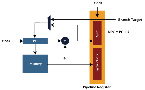
Stage 2: Stage 2 is the instruction decodes stage. Here instruction is decoded, and control signals are generated for the opcode bits. In this stage, the source operands are read from the register file. With the help of specifiers, the indexing of register file is done. The pipeline register will send the operands and immediate value to the next stage. It will also pass NPC and control signals to the next stage. The process of instruction decoder stage is described as follows: 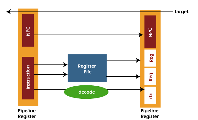
Stage 3: Stage 3 is the Instruction executes stage. The ALU (arithmetical logical unit) operations are performed in this stage. It takes the two operands to perform the ALU operation. The first operand is used to contain the content of a register, and the second operand is used to contain either immediate value or a register. In this stage, the branch target can be computed with the help of following formula: The pipeline register (PR) will update the ALU result, branch target, control signals, and destination. The process of instruction execution is described as follows: 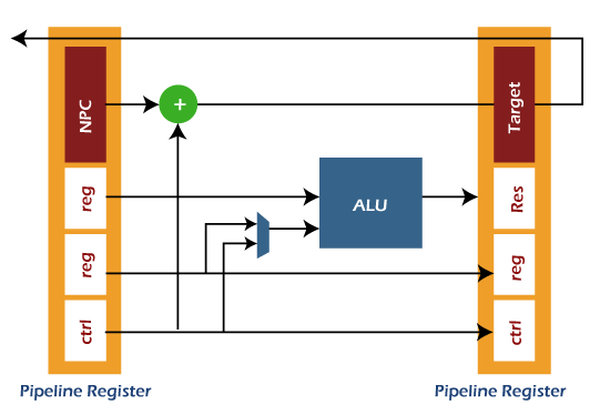
Stage 4: Stage 4 is the Memory Access stage. Here, memory operands are able to read and write to/from memory, which exists in the instruction. The pipeline register (PR) will update the ALU result from execution, destination register, and loaded data from D-Memory. The process of memory access is described as follows: 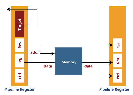
Stage 5: Stage 5 is the Write Back stage. Here, the fetched value is written back to the register, which exists in the instruction. This stage only needs one write part, which can either be used to write the loaded data into the register file or to write the result of ALU into the destination register. 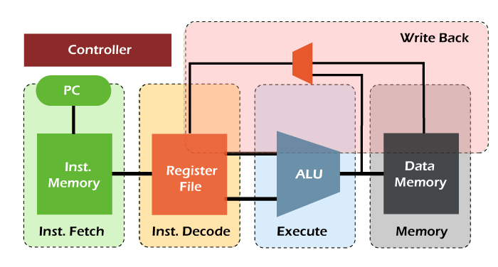
Performance of Pipelined processorHere we will assume a segment pipeline as 'k' and the clock cycle time 'Tp'. Suppose the pipeline processor needs to complete the 'n' number of tasks. Now the first instruction will come out from the pipeline by taking the 'k' cycle. On the other hand, 'n-1' instructions will take only '1' cycle each. That means the 'n-1' instruction will take the total 'n-1' cycle. In a pipeline processor, when we try to execute the 'n' instructions, then the time taken to do this is described as follows:
ET pipeline = k + n -1 cycle
         = (k + n -1) Tp
In a non-pipeline processor, when we take the same case and try to execute the 'n' instructions, then the time taken to do this is described as follows: ET non-pipeline = n * k * Tp So, when we perform 'n' tasks on the same processor, the speedup (S) of pipeline processor over non-pipelined processor is described as follows: S = Performance of pipeline processor / Performance of Non-pipelined processor As the execution time and the performance of process is inversely proportional to each other. So we have the following relation: S = ET non-pipeline / ET pipeline S = [n * k * Tp] / [(k + n -1) * Tp] S = [n * k] / [k + n - 1] The following relation will contain if the n number of tasks is larger than 'k' that means n >>k. S = n * k / n S = k Here K is used to indicate the number of stages in the pipeline. Also, Efficiency = S / Smax Here S is used to show the max speed up, and Smax is used to indicate the Maximum speed up. We know that Smax = k So, Efficiency = S / k Now throughput can be described like this: Throughput = Number of instruction / Total time to complete the instruction So throughput = n / (k + n + 1) * Tp Note: For the ideal pipeline processor, the value of Cycle per instruction (CPI) is 1.Pipeline ConflictsThe performance of pipelines is affected by various factors. Some of the factors are described as follows: Timing Variations We know that the pipeline cannot take same amount of time for all the stages. The problem related to timing variation will occur if we are processing some instructions where different instructions need different operands and take different processing times. Data Hazards The problem of data hazards will occur when there is parallel execution of several instructions, and these instructions reference the same data. So we should be careful that the next instruction does not try to access the data which is already accessed by the current instruction. If this situation arises, it will generate the incorrect result. Branching We should know about the instruction before we try to fetch and execute the next instruction. Suppose there is a case in which the current instruction contains the conditional branch, and the result of this instruction will lead to the next instruction. In this case, we will not be able to know the next instruction as long as the current instruction is proceeding. Interrupts Because of the interrupts, the unwanted instruction will be set into the instruction stream. The execution of instruction is also affected by the interrupt. Data dependency The situation of data dependency will occur when the result of previous instruction will lead to the next instruction, and this result is not yet available. Advantage of Pipelining
Disadvantage of Pipelining
Next TopicTypes of Pipeline Delay and Stalling
|
 For Videos Join Our Youtube Channel: Join Now
Feedback
- Send your Feedback to [email protected]
Help Others, Please Share


