| |

Frequency Modulation (FM)When the frequency of the carrier wave varies with the amplitude of the message signal, it is called frequency modulation. It is a type of angle modulation, a non-linear modulation process. The superimposition of the two waves does not work in FM. The carrier signal is sent with the message signal during the modulation process. A message signal is also known as the baseband signal. It is nothing but a signal containing information that needs to be transmitted from the sender to the receiver. A sender in the communication system is known as a transmitter. Before beginning with FM, let's fist discuss the concept of modulation and the use of carrier signals during the modulation process. ModulationModulation refers to converting the information signal to a suitable form of transmission. In communication system, the message or the information signal is converted to the electronic signal, which is transmitted through the communication channel to the receiver. The receiver performs the demodulation process and converts the electronic signal back into its original form. Carrier signalThe carrier signal and the message signal share the same medium of propagation. It also allows carriers of different frequencies to transmit, which gives rise to multiplexing, the method to transmit multiple signals effectively over the same communication channel. The high-frequency carrier is also used in various modulation processes because it travels with high speed and allows the message signal to travel long distances. If the carrier is suppressed during the modulation for improved efficiency, it can be further added afterward. This technique is known as the coherent detection method and is commonly used in amplitude modulation techniques, such as DSBSC (Double Sideband Suppress Carrier Modulation), SSBSC (Single Sideband Suppress Carrier Modulation), and VSBSC (Vestigial Sideband Suppress Carrier Modulation). Here, we will discuss the following: What is FM? Bessel's coefficient Bandwidth of FM Spectrum of FM Types of FM FM Modulator FM Demodulators Applications of FM AM vs. FM FAQs What is FM?FM or Frequency Modulation is a modulation that operates in the region of high frequency and has high bandwidth. It operates in the VHF (Very High Frequency) range and can travel long distances. The FM modulated signal produces an infinite number of sidebands resulting in infinite bandwidth. FM has two types, Wideband FM and Narrowband FM. The Wideband FM has wider frequency bands with a wide range of frequencies, and narrowband FM has narrow bands operating in a short range of frequencies. Both have their applications and advantages. FM's modulation and demodulation process are similar to the AM modulation and demodulation process except for the integrator and differentiator required to generate FM and PM signals. The information in FM is transmitted in the form of radio waves from the transmitter to the receiver. The waveforms of the message signal and the FM signal are shown below: 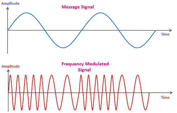
Bessel's coefficientBessel's coefficient generally determines the amplitude of the spectral components in the modulated signal. It is represented by β, and is given by: Jo (β) = 1 - (β/2)2 Where, Jo represents the magnitude of the function At β = 0 Jo (β) = 1 - (0/2)2 Jo (β) = 1 Thus, when there is no modulation, only the carrier is present while all the sidebands have zero amplitude. For a very small value of β, the FM signal contains a carrier and one pair of sidebands with sum and difference frequencies ωc - ωm and ωc + ωm . Such type of FM is called as narrowband FM. When the value of β increases, the magnitude of the signal increases. Thus, the second pair of sidebands become significant. Similarly, further pairs of sidebands increase with the increase in value of β at frequencies ωc ± 2ωm, ωc ± 3ωm, and so on. The power of the FM signal is constant because it depends on the envelope of the FM signal, which has a constant amplitude. Power is proportional to the square of the amplitude instead of frequency. P = 1/2 It is independent of β and modulation. Power in terms of Bessel's magnitude function (J) is given by: P = 1/2 (JO2 + J12 + J22 + J32 + J42 + J52) At various values of β, Jo (β) = 0. It means that the entire power lies in the sidebands and no power is present in the carrier. Bandwidth of FMThe bandwidth of FM is very large as compared to the bandwidth of AM. The bandwidth of FM is infinite due to the presence of infinite pairs of sidebands produced during the modulation process. Hence, a large fraction of the total power of FM is limited to its sideband. There is no serious distortion if the sidebands outside the bandwidth range are lost. The distortion from a bandlimited signal is acceptable if atleast 98% of the total power is passed by the band limiting filter. The power of FM by equating the Bessel's coefficient equal to 1 (β = 1) is given by: P = 1/2 (JO2 + J12 + J22) P = 0.495 P = 0.5 (Approx) It is equal to 1/2 Thus, the bandwidth required to transmit the FM signal is given by: BW = 2(β + 1)fm Bandwidth in terms of modulating frequency and frequency deviation can be expressed as: BW = 2(Δf + fm) Bandwidth is equal to sum of frequency deviation and modulated frequency. Where, fm is the modulated frequency Δf is the frequency change or frequency deviation Let's discuss the spectrum of the FM signals for various value of Bessel's coefficient. The spectrum for β = 1, 5, 10, and 20 is shown below: 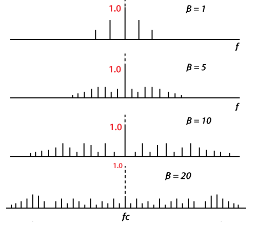
Types of FMIn Double Sideband Amplitude Modulation, the two sidebands of frequencies ω + ωc and ω - ωc are produced. But FM generates infinite number of sidebands resulting in infinite bandwidth. FM is categorized as:
Narrowband Frequency ModulationAs the name implies, narrowband FM has narrow bandwidth. It occupies only a small portion of the FM signal and uses the small range of frequencies. The advantages of using Narrowband modulation are lower noise and improved sensitivity. Hence, it is commonly used in short distant communication ad fixed location wireless transmission. The modulating waveform in AM is given by: V(t) = A[1 + m(t)] cosωct Where, A is the amplitude constant ωc is the carrier frequency m(t) is the message signal. It is the signal with finite energy. The modulating waveform in FM is given by: V(t) = Acosωct + Am(t)sinωct If the message signal m(t) in FM is of finite energy, the spectral power densities of the both the Amplitude modulation and frequency modulation would be the same. Wideband Frequency ModulationAs the name implies, wideband FM has wider bandwidth. It occupies a large portion of the FM signal and uses a wide range of frequencies. The advantage of using Wideband Frequency Modulation is its ability to transfer high data rates. Hence, it is commonly used in long-distance communication, broadcast FM stations, and quality radio transmission. The parameter that determines the signal being Narrowband or Wideband is given by: β = Δf / fm Where, fm is the modulated frequency Δf is the frequency deviation Β is the Bessel's function The signal is Narrowband if β << 1 The signal is Wideband if β >> 1 FM ModulatorModulation is the technique to convert the data to the suitable form of transmission. It also increases the characteristics of the signal by sending the message signal with the high-frequency carrier signal like AM. There are two methods to perform the FM modulation, the Parameter variation method and the Armstrong Indirect Method. Let's discuss these two FM modulation techniques in detail. Parameter Variation MethodThe tuned circuit oscillator generally produces the carrier of the FM signal. It is an LC oscillator containing an inductor (L), and a capacitor (C) connected in parallel. Its frequency is nearly equal to the resonant frequency of the inductor and capacitor combination. The frequency of oscillations of the tuned circuit oscillator is given by: 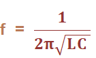
The circuit is shown below: 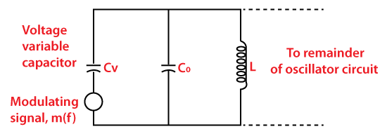
A voltage variable capacitor Cv is connected in parallel with the fixed capacitor Co whose value depends on the dc biasing voltage maintained across the electrodes (positive and negative) of the semiconductor diode. The modulating signal m(t) is connected in series with the capacitor Cv. It varies the variable capacitor connected across it, which further changes the oscillating frequency of the tuned circuit. The change in the oscillating frequency is very small due to the small voltage change by the message signal. Thus, we can say that the instantaneous value of the oscillating circuit depends on the instantaneous frequency of the message signal. Such type of oscillators is also known as VCO (Voltage Controlled Oscillator). Armstrong Indirect methodThe Armstrong indirect method is a modulation technique for both FM and PM (Phase Modulation) except the added requirement of an integrator to produce the FM signal. The circuit of the Armstrong system for generating PM signal is shown below: 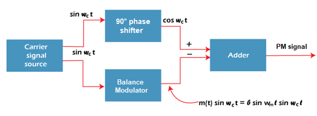
The circuit consists of a carrier signal source, balance modulator, 90 degree phase shifter, and an adder. The function of the carrier signal source is to generate a carrier sinωct with the carrier frequency ωc. The 90 degree phase shifter converts the carrier signal sinωct to cosωct. A balance modulator generates a double sideband amplitude modulated signal by superimposing the message and the carrier signal sinωct. The output signal is generally a suppressed carrier signal. The carrier shifted by a phase of 90° when added to the output of the balanced modulator forms an NBFM (Narrowband Frequency Modulation) signal. But, the generated signal is a phase modulated signal. For FM signal generation, we need an integrator connected before the modulator. It will integrate the incoming modulating signal before sending it to the modulator. The circuit of the Armstrong system for generating FM signal is shown below: 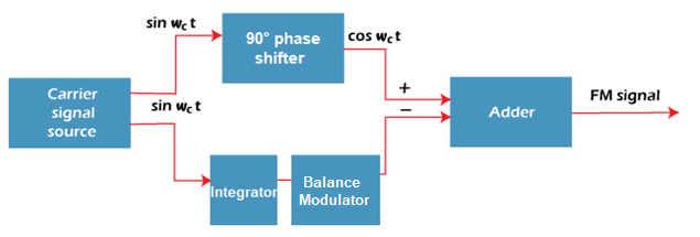
The above circuit consists of a carrier signal source, integrator, balance modulator, 90 degree phase shifter, and an adder. The function of the carrier signal source is to generate a carrier sinωct with the carrier frequency ωc. The integrator integrates the carrier signal sinωct before sending it to the balance modulator. A balance modulator is generates a DSBSC signal using the carrier sinωct. The carrier shifted by a phase of 90° when added to the output of the balance modulator forms a NBFM (Narrowband Frequency Modulation) signal, which is a frequency modulated signal. Frequency MultiplicationIt is the method to increase the frequency deviation of the FM signal. The circuit used for the frequency multiplication consists of a non-linear element (such as transistors) and a bandpass filter. One such combination of a BJT (Bipolar Junction Transistor) and a bandpass filter (resonant LC circuit) is shown below: 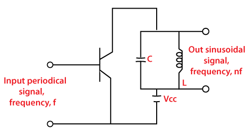
The transistor works in the cut-off region for more than half of the input signal. During the intervals, it operates in the saturation region. For each input cycle, the collector current flows and form pulses. The resonant circuit formed from the parallel combination of inductor and capacitor. To increase the frequency deviation, we will use crystal oscillators and multipliers in addition to the block diagram circuit of the Armstrong indirect method of FM generation. The multiplication is performed with the help of a multiplier. To achieve higher order of multiplication, the multipliers are arranged in the series combination. The circuit is shown below: 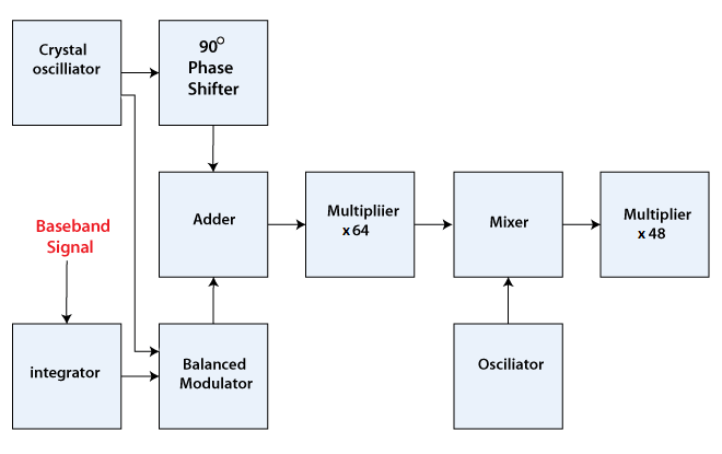
The output of a mixer is the sum and difference of the message and carrier frequencies. It will not create any affect in the frequency deviation of the FM signal. The chain of multipliers in the circuit helps in the accomplishment of the frequency translation. The use of multipliers reduces the cost of the FM modulators and consumes less power. FM DemodulatorsDemodulation is a process to recover the original message signal. There are two methods to recover the message signal from the frequency selective carrier, frequency selective method and a pulse averaging discriminator. Frequency selective carrier methodThe circuit representation is shown below: 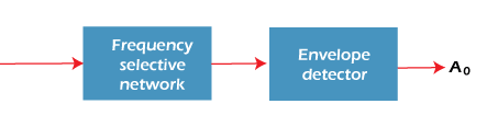
It consists of a frequency selective network and the envelope detector. The input FM modulated signal has an input amplitude Ai and yields an output Ao. The output wave generated by the frequency selective method is both frequency modulated and amplitude modulated. The diode demodulator responds only to the amplitude modulated signal and ignores the frequency modulation. The allowable frequency deviation is: Δf = β ωm/2π Any demodulator cannot achieve the desired linear characteristics. Hence, we consider a balance FM demodulator that reduces the distortion and harmonics produced by the bandpass filters. The frequency should be proportional to the instantaneous frequency of the received FM signal. The circuit of a balanced demodulator is shown below: 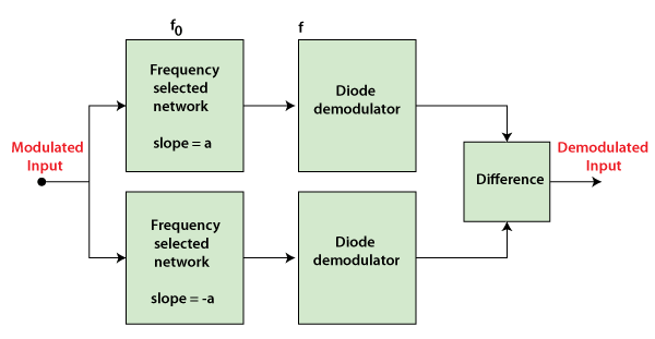
Here, we have used two frequency selective networks, which only differ in terms of the slope. Both networks have a slope of α and -α. The difference output is given by: Ao = 2αAi (f - fo) The output of the balance modulator is the difference between the outputs of the two individual demodulators. Pulse averaging discriminator methodThe pulse averaging discriminator is an IC (Integrated Circuits) based demodulation technique. The circuit consists of a zero crossing detector, a monoshot vibrator, and a low pass filter. We can also use a hard limiter instead of a zero crossing detector. These three devices are connected in a cascade. The monoshot vibrator produces the single output pulse either HIGH or LOW of certain width. For example, the low pass filter (an RC circuit) allows a certain range of frequencies to pass through it. The zero crossing detectors can detect the transition of the waveform from positive to negative. The circuit of pulse averaging discriminator is shown below: 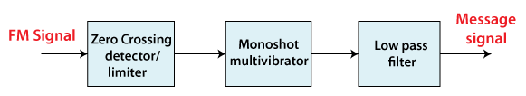
When the FM modulated carrier signal is applied to the zero crossing detectors, it produces rectangular pulses. The frequency of these pulses depends on the instantaneous frequency of the FM signal. The output of the detector is sent to the monoshot vibrator that produces the pulse of fixed width. The low pass filter further produces the time averaging of the dc pulses. If the frequency of the input signal is high, the average output will be high. If the frequency of the input signal is low, the average output will also be low. 
PLL (Phase Locked Loops)PLL is one of the FM demodulators that help in recovering the information from the original FM signal. It works on the concept of the phase of two signals and minimizes the differences between them. A VCO (Voltage Controlled Oscillator) in the PLL circuit generates a reference signal of frequency equal to the carrier frequency. PLL also uses phase-locked ICs (Integrated Circuits) for FM demodulation. It is used in many applications, such as broadcast receivers, motor speed controls, and clock recovery. Applications of FMThe applications of Frequency Modulation are as follows:
AM vs. FMAM and FM are both categorized under analog communication. The transmission process of analog communication consists of a transmitter, communication channel, and a receiver. Modulation is the process of increasing and enhancing the frequency and strength of the message signal. It modulates the incoming signal, which is a part of the transmitter. The original signal is recovered at the receiving end, which is known as demodulation. Modulation and demodulation are the essential part of every modulation technique, such as AM (Amplitude Modulation), FM (Frequency Modulation), and PM (Phase Modulation). It also removes any noise or attenuation in the signal that arises during the transmission process. FM is also used in digital communication, termed FSK (Frequency Shift Keying). The waveforms of the modulation techniques are generally represented as a sine wave, which represented a natural changing state of most objects. A sine wave can easily depict amplitude, frequency, and phase changes with time. It repeats its cycle after every 360 degrees or 2π radians. Amplitude ModulationThe message signal, also known as the baseband signal, is superimposed on the high-frequency carrier wave. It produces the amplitude modulated waveform with the improved frequency. When the amplitude of the carrier wave varies with the amplitude of the message signal, it is called amplitude modulation. The process of amplitude modulation is shown below: 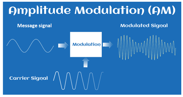
It depicts how the high-frequency carrier signal superimposes on the original message signal, resulting in an amplitude-modulated waveform. There are various methods to modulate the AM signal. A simple example uses the balance modulators and an adder, which modulates the signal, removes the noise, and suppresses the carrier. The suppressed carrier method provides better efficiency as compared to other modulation techniques. Modulation offers other advantages, including multiplexing and effective transmission upto long distances with the help of an antenna. Amplitude Modulation is used in various applications, such as electronic communication and radio communication. The differences between Amplitude Modulation and Frequency Modulation are listed in the below table:
FAQsLet's discuss some frequently asked questions. Question 1: Which type of analog modulation technique has better noise immunity?Answer: FM Noise immunity refers to the ability of a system to get less affected by the noise. Frequency modulation (FM) has very little noise because the frequencies of radio waves have better quality and less noise than that of the amplitude of the radio waves. Hence, FM is a better modulation technique in terms of noise immunity than other modulation techniques. Question 2: Is FM signal preferred for long distances transmission? If not, then which type of modulation is preferred?Answer: No FM signal is not preferred for long distance transmission. FM has good reception ability of for only short distances transmission. AM (Amplitude Modulation) is preferred fo4r long distance transmission due to its various advantages, such as easy modulation, demodulation, and low cost. Question 3: Why the bandwidth of FM is infinite?Answer: The bandwidth of FM in infinite because it produces infinite number of sidebands, while amplitude modulation produces only a single pair of sidebands.
Next TopicFM vs PM
|
 For Videos Join Our Youtube Channel: Join Now
Feedback
- Send your Feedback to [email protected]
Help Others, Please Share


