Hatch Command in Solid Works
To fill enclosed spaces or certain entities with a hatch pattern, use the -Hatch command.
A drawing's hatching provides depth and clarifies the materials and places. Some drawing applications, such as construction drawings, call for hatch patterns that can improve a design's clarity and readability.
By choosing the Solid option from the Pattern list, you may apply solid hatches in addition to patterns to fill up a bound region with the current colour.
It is the Hatch command's command window version.
Do the following to hatch an area:
- Define the limit.
- Select a hatch pattern other hatch display options (annotative scaling, placement, transparency)
- Configure extra hatch boundary detection options
How to make a hatch
- At the command prompt, type -Hatch.
- Choose from the following possibilities:
- Provides extra choices for filling in gradients and hatches. You have additional choices to manage open areas, internal regions, and the connection between the hatch and the boundary.
- Determines whether annotation scaling will be used when creating or editing the hatch. Hatch entities automatically preserve the hatch size when you scale Viewports on Layout Sheets. Similar pattern sizes in Viewports on layout Sheets are guaranteed by this attribute.
- Create boundary: This feature enables you to construct borders similarly to how you would draw a polyline. You may decide whether the hatch pattern automatically updates if the hatch border shifts.
- Deselecting a boundary de-selects all the boundary's defined entities.
- Choose a predefined, user-defined, or solid hatch pattern using the pattern option. The current colour is filled into the confined region by a solid hatch.
- Pattern start: Allows you to select the beginning of the hatch pattern.
- Allows you to specify where the hatch should be in reference to the limits.
- Entities to specify: Allows you to choose the entities that make up the border or already-existing closed contours to act as the boundary.
- Allows you to choose the amount of transparency for the fill or hatch.
Name the Boundary.
There are several ways to establish the boundary:
- Creating the border using a polyline as a comparison.
- Choosing the entities that make up a confined region.
- Choosing a point inside a closed region: In order to establish a border entity, at least one point must be specified inside a closed area. Add more internal points to build extra border entities.
To delineate hatch pattern boundaries:
- Enter after selecting the Create boundary option.
- Type Yes or No to indicate if you wish to preserve the original boundaries. Enter the key.
- Set the beginning of the first border segment in the graphics area.
- Provide alternatives for the next portions.
- Arc: The segment type is changed to an Arc. The boundary segment can be drawn in the same manner as a polyline's arc segment. See Building Polylines.
- Indicate the segment's length.
To undo the most recent drawing action, use the Undo option. The Undo function can be used repeatedly.
- Indicate where the section ends.
- Do one:
- Each subsequent section should be specified using steps 4 and 5.
- Choose the Close option to establish a closed border after entering at least two segments, or just press Enter.
By choosing entities, you may define boundaries:
- Type Enter after specifying.
- Identify the items that make up the boundaries in the graphics area.
- or -
Indicate the selection process (choose from the choices below):
- Choose an interior point to define the bounds of enclosed spaces. To establish a border entity, at least one point must be located inside a closed region.
- Add more internal points to build extra border entities.
- Removes chosen entities from the boundary definition when you deselect a border. You can exclude limits from selection if you have already chosen them to hatch. Use Add bounds to choose more borders.
- Enter the key.
- You can specify the border before setting the hatch pattern.
To remove existing borders and add new ones:
- Put "Deselect boundary" in the options. The border specification is modified to exclude specific things.
- Enter the entities for the new bounds in the graphics section.
- or -
Choose the new limits:
- Enter after selecting the Add boundaries option.
- To draw the borders in enclosed spaces, click points.
A Hatch Pattern's Setting
You may fill sections with a certain hue or hatch them using a variety of hatch patterns.
By default, the hatch pattern begins at the drawing's origin when hatching a closed region. To draw the hatch starting from a different starting point at a suitable position, you may specify the starting point.
Creating a hatch pattern
- Enter after typing Pattern.
- Name the sort of pattern:
- established pattern
- Insert the pattern name after providing it
- or -
- To view a list of the available premade patterns, use the? Option.
- Customer specified
- Enter after typing User.
- Press Enter after entering a hatch pattern angle.
Typical hatch designs are composed of straight, angled, or horizontal or vertical lines. A horizontal line is defined by a hatch angle of 0 degrees. The pattern spins anticlockwise when the angle is positive.
- Press Enter after entering the line spacing for the hatch pattern.
- Be sure to provide the distance in drawing units (default is 1). To alter the pattern proportions for graphic regions, alter the line spacing.
- Type Yes or No to indicate if you wish to include intersecting lines. Enter the key.
- Solid: Enter after typing Solid.
Define the borders to hatch after choosing the pattern or choose another choice.
To determine where to start the hatch pattern:
- Press Enter after typing "Start."
- One of the following choices should be chosen as the pattern start point:
- Currently being drawn: the existing hatch origin is preserved (default).
- Place defined by the user: Establishes the hatch origin at a predetermined point.
- Set a point in the graphics area.
- Type Yes or No to indicate whether you wish to set the provided location as the default. Enter the key.
- Use Boundary encompasses:
- Choose between the Center and one of the border corners (Top Left, Top Right, Bottom Left, and Bottom Right).
- Enter the key.
- Type Yes or No to indicate whether you wish to set the provided location as the default.
To remove existing borders and add new ones:
- Put "Deselect boundary" in the options. The border specification is modified to exclude specific things.
- Enter the entities for the new bounds in the graphics section.
- or -
Choose the new limits:
- Enter after selecting the Add boundaries option.
- To draw the borders in enclosed spaces, click points.
Adding More Choices to the Hatch Display
Use the following alternatives if you'd want to improve how hatched entities are shown and selected:
- Placement: To make choosing the hatch border easier, the hatch is by default built behind the hatch boundary. The hatch can be built behind or in front of any other entity, as well as the border for the hatch.
- You may adjust the hatch's transparency to see the objects below it more clearly. This choice is advantageous, particularly for solid fills.
- While creating or editing the hatch, you may choose whether the annotative scaling should be used. Hatch entities automatically keep the hatch size when you alter the scale of Viewports on Layout Sheets.
To describe the location:
- Placement, then hit Enter.
- Choose from the following choices:
- Bringing in front of the border the hatch is put in front of the border. Specify Boundary and hit Enter.
- Bring forward: in front of all other entities, the hatch is put. Front, then hit Enter.
- Avoid assigning: While typing not, hit Enter.
- Send behind boundary: Positions the hatch there. After typing behind, hit Enter.
- Sets the hatch behind all other entities by sending it to the back. Enter after typing back.
Hatch transparency level specification:
- Press Enter after entering Transparency.
- Set the degree of transparency. Set the value between 0 and 90%, with 0% denoting complete transparency (opaque).
- or -
Choose from the following choices:
- Use current: For new entities, it applies the current transparency option.
- By Layer: Uses the transparency setting for the current layer.
- If the hatch or fill is contained in a block, ByBlock: Uses the block's current transparency setting.
Annotative hatch making:
- Type "Annotative" and hit Enter.
- Type Yes or No to indicate if you wish to construct an annotative hatch. Enter the key.
Configuring Extra Hatch Boundary Detection Options
The command recognizes the things that make up the border when establishing hatch boundaries by specifying internal points. In this instance, extra settings let you manage the automated boundary detection.
More choices to set hatch to establish the border
- Enter after specifying Extra options.
- Choose from the following choices:
- Boundary group: This feature enables you to specify the entities that will be considered when choosing a boundary using an internal point.
Choose from the following choices:
- Choose entities for the border with the new group.
- Enter after specifying the entities in the graphics area.
- Everything: Constructs a border group from all things that are visible in the active viewport.
- Gaps: Allows you to select the largest size of gaps that can be disregarded between boundary entities before the border is deemed to be closed.
- Hatch per border: Type Yes or No to indicate if you want to build a hatch for each boundary. Enter the key.
- Type Yes or No to indicate if you wish to look for internal closed borders in internal areas. Enter the key.
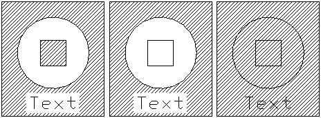
- Specify the method used to hatch entities inside the border using the region style option. Choose from the following possibilities:
- Out: Just produces hatch patterns near the very edges.
- In/Out: Starts with the outermost region and creates a hatch pattern between alternating sections (default).
- Ignore: Ignores the area's internal structure and completely hatches it. Hatch lines can pass over 2D solids, text, and block characteristics.
The In/Out, Out, and Ignoring styles are depicted in the diagram below.
- Maintain boundaries: Type Yes or No to indicate if you want to keep the initial closed contour. Enter the key.
- Type Yes or No to indicate whether you wish to attach the hatch to the border. Enter the key. If the hatch's perimeter changes, the hatch automatically adjusts.
- To configure other parameters as needed, repeat the previous procedure.
- Enter the key.
Putting up hatches
To fill enclosed spaces or certain entities with a hatch pattern, use the Hatch command. A drawing's hatching provides depth and clarifies the materials and places.
Some drawing applications, such as construction drawings, call for hatch patterns that can improve a design's clarity and readability. By choosing Solid from the Pattern list, you may apply solid hatches in addition to patterns to fill up a limited region with the current color.
To alter current hatch patterns, see Customized Hatch Patterns.
Do the following to hatch an area:
- Organize a hatch pattern.
- Set the scale and the angle.
- Set the hatch's initial position.
- Define the limit.
Creating a hatch pattern
- Choose Hatch/Fill under Draw (or type Hatch).
- Choose a pattern type from the Type list in the Hatch/Fill dialogue box.
- It allows you to choose from predefined patterns, including designs that adhere to ISO and ANSI standards as well as patterns that are often used sectors.
- User-defined. It allows you to choose a pattern that you or your company designed.
- It allows you to specify a pattern based on your specified Angle and Spacing.
- Choose a pattern if you choose a Predefined type from the Pattern list.
The selected pattern is shown in the Preview window next to the Pattern list.
Instead, you may click to open the Choose Pattern Style dialogue box and choose a type and a pattern there.
To scale the hatch design and determine its angle:
1. Set the angle for the hatch pattern in the Angle list.
Typical hatch designs are composed of straight, angled, or horizontal or vertical lines. A horizontal line is defined by a hatch angle of 0 degrees. Angle values between 0 and 360 are available in 15-degree increments in the Angle list. The pattern spins anticlockwise when the angle is positive.
2. To scale the hatch pattern, enter a value in the Scale list.
Values between.25 and 2 are available on the Scale list in.25-unit increments (default is 1).
For instance, 2 doubles the pattern's distances while.25 cuts its initial size in half.
User-defined patterns cannot be resized, please note. Use the Spacing list to modify the distances in user-defined patterns.
3. If you chose a User-defined type, enter the distance between the lines in the hatch pattern under Spacing.
Be sure to provide the distance in drawing units (default is 1). To alter the pattern proportions for graphic regions, alter the line spacing.
4. Use the ISO pen width list to choose a pen width if you chose an ISO Pattern type.
5. To adjust the units to the sheet, choose Scale based on sheet's units.
To determine where to start the hatch pattern:
- One of the following should be entered as the Pattern start point:
- Genesis of the current drawing: The existing hatch origin is preserved (default).
- User-specified place. To specify coordinates, click. To designate a point in the graphics area, enter coordinates or choose a place from the Use border list. By clicking Set as default, the chosen location will be saved.
To establish limitations on hatch patterns:
- Choose a technique to specify borders in Boundary settings:
- Name the entities. Name the entities: Allows you to choose the boundary-forming entities.
- Provide points including points: Allows you to establish borders by clicking points inside of enclosed spaces.
- Repair the border Rebuild the border: After deleting a barrier, replaces it (enabled only when using the Edit Hatch command).
- Remove the boundary objects Remove the border objects.
To further individualize the hatch pattern choices:
Provide extra border and hatch options:
- See Adding More Hatch and Gradient Fill Choices (annotative scaling, placement, transparency).
- To learn more, go to Establishing Behavior Choices for Hatch and Fill Boundary.
Color gradient fills creation
To fill a closed region or certain entities with a solid color or a color gradient, use the Fill Area command.
Color fills, like hatches, provide designs with more meaning and aid in identifying different types of objects and spaces.
To add color to a fill:
- To hatch or fill, select Draw (or type Fill Area).
- Choose Fill from the Hatch / Fill dialogue box.
- By picking one color or two colors, choosing a color by clicking, and then using the Dark Light slider, you may customize the gradient's color scheme.
Note: Click One Color, then type 50 in the space next to the Dark-Light slider to get a consistent solid fill.
- Choose a style for a color gradient from the Style list:

- Adjust Orientation to guarantee that the pattern is symmetric inside the bounds by setting the Angle and, if desired, choosing Symmetric.
- Set the Boundary parameters.
- Name the entities. Name the entities. Allows you to choose the boundary-forming entities.
- Provide points including points. Allows you to establish borders by clicking points inside of enclosed spaces.
- repair the border Rebuild the border. after deleting a barrier, replaces it (enabled only when using the EditHatch command).
- Remove the boundary objects Remove the border objects. borders are eliminated from the collection of elements that make up the boundaries.
- Showcase border elements accentuate the border elements. displays the drawing's bounds.
- Set optional extra parameters:
- See Gradient Fills and Hatches More Options.
- To learn more, go to Establishing Behavior Choices for Hatch and Fill Boundary.
- To see the colour settings before applying them, click Preview.
- To apply the fill settings, click OK.
Editing Fills and Hatches
You may alter gradient colour fills, solid colour fills, and hatch patterns. The group of entities to be hatched or filled can then be expanded with more.
Editing a color fill or hatch pattern
- Click Modify > Entity > Hatch (or type Edit Hatch) (or type Edit Hatch).
- Name a current hatch.
- Choose Hatch to update the hatch or fill to update the colour fill in the Hatch/Fill dialogue box.
- To the list of entities to be modified, you may also add further entities.
Choose either Hatch or Fill in the Hatch/Fill dialogue box, then choose the pattern or fill you wish to use, to transform a hatch into a fill or vice versa.
|

 For Videos Join Our Youtube Channel: Join Now


