| |

How to make a drawing from a part NXUsing the NX Drafting tool, you may generate a 2D sketch from a 3D model. In this simple example, we will utilize the 3D model shown in Figure 1. 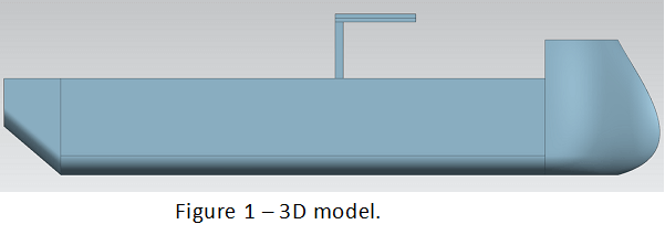
First, we must launch the Drafting application. Navigate to File > Drafting while the 3D model is open in NX. This turns off the Modelling programme and launches the Drafting application. 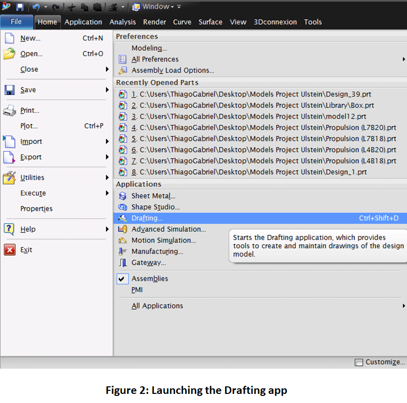
When you run the Drafting application, the Sheet dialogue window (figure 3) will display. Here, you may select from pre-defined templates for the document or build a new one. The Populate Title Block dialogue window (figure 4) will display once you pick the sheet. Here, in the lower-right corner of the page, you may define some sketching primary identifying fields. 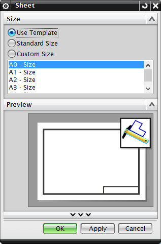
Figure 3 shows the Sheet Dialogue window. 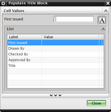
Figure 4: The Populate Title Block dialogue box. The 2D drawing can be added after the paper has been properly specified. The View Creation Wizard button (figure 5) can be used to add a desired view to the drawing paper. 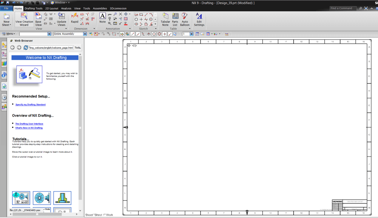
Figure 5 shows how to add the desired view. The tab Portion (figure 6) allows you to pick the part for which you want a 2D depiction. In this instance, the full assembly will be chosen. 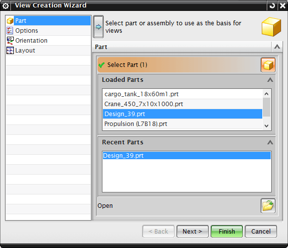
Figure 6: Choosing the desired portion. The draw scale ratio, as well as various variables for lines and preview style, may be selected via the Options tab (figure 7). 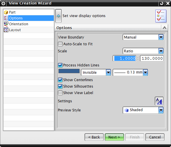
Figure 7: Changing the 2D draw aspect. Over the Orientation tab (figure 8), you may choose the view you want to create, including three-dimensional views like Isometric. 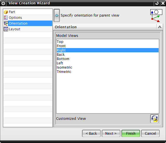
Figure 1: View selection. Over the Layout tab (figure 9), you can choose the placement technique and whether or not to add any extra views to the drawing. 
Figure 9 shows the Layout tab. Figure 10 depicts the outcome of the view development process. 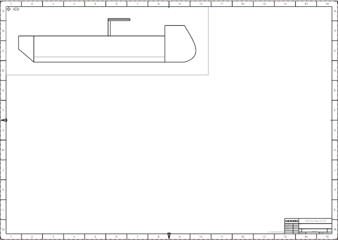
Figure 10: A 2D representation of the 3D model. Section views can also be added to further detail the model. This is accomplished by using the Section View button, as illustrated in Figure 11. 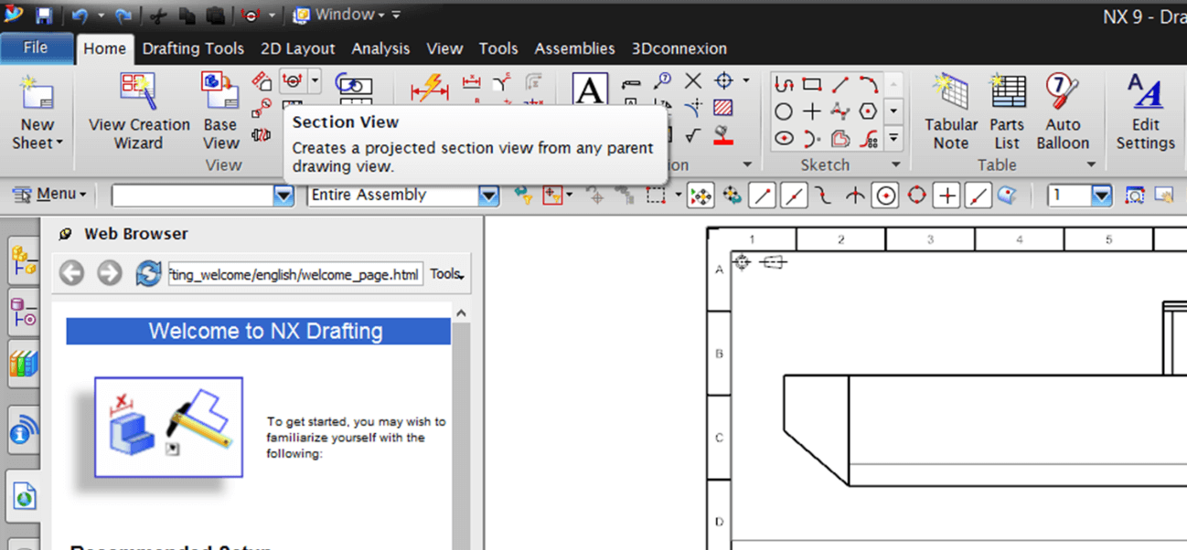
Figure 11 shows the Section View tool. The placed view should be selected once the Section View dialogue windows appear. As a result, a hinge line (shown in orange in figure 12) defining the cross section to be projected should be set at the required location above the placed view. The black arrows at the ends of the hinge line require special attention. They indicate the direction in which you should be gazing at the projected segment. The direction can be switched if required by utilizing the Hinge Line option in the Section View dialogue windows. 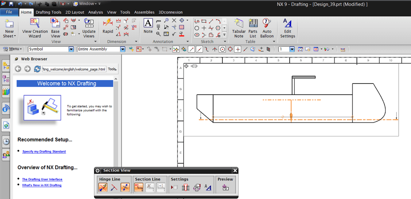
Figure 12: Establishing the plane of vision. After selecting the segment, position it over the paper sheet as illustrated in figure 13. Repeat this method until all of the model's essential portions are represented. 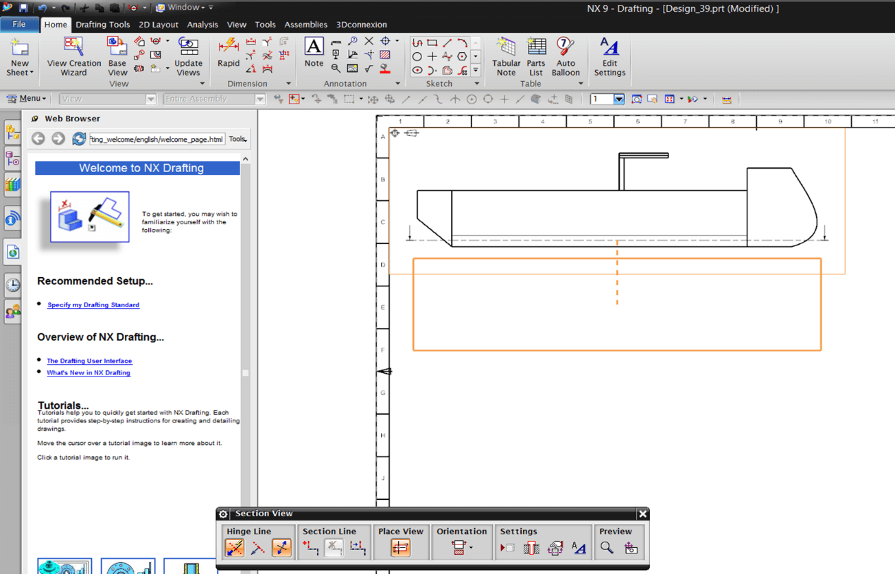
Figure 13: Aligning the perspective. Figure 14 shows an example of a finished 2D design with section views. 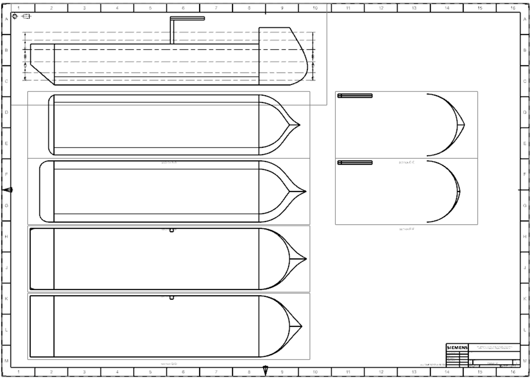
Figure 14: The finished version of the first example. The fundamentals of sketching in NX
Modeling is divided into two ways. One is to set your geometry to 0,0,0 for all components that will be placed in parent assemblies. The alternative is to be in X-coordinate space, where X is the controlling coordinate of the parent. For example, consider aircraft or vehicle coordinate space. Let's start with where you should begin your portion!
This is often true for any item that may be utilized in many locations or assemblies, independent of the coordinate space in which you are working.
Next TopicInsert a Drawing Into a Template
|
 For Videos Join Our Youtube Channel: Join Now
Feedback
- Send your Feedback to [email protected]
Help Others, Please Share


