How to Trim in SolidWorks
Reduced Entities
Based on the entities you wish to trim or expand, choose the trim type. Using 2D drawings and 2D sketches on 3D planes, all trim kinds are possible.
- Any of the following trim choices are available:
- Corner power trimming
- Trim the inside
- Remove excess exterior
- Reduce to nearest
Also, use:
- As building geometry, keep the cut entities.
- Ignore construction geometry trimming
Using Power Trim to trim
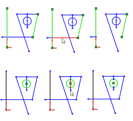
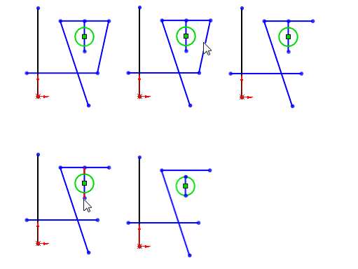
Drag the cursor over each drawing item to utilize Power trim to cut several, neighboring sketch elements.
With the Power trim option, trim:
Edit Sketch may be chosen by right clicking the sketch.
Click Tools > Sketch Tools > Trim or Trim Entities Tool Trim Entities Sketch.gif (Sketch toolbar).
Choose Power trim PM trim power trim.gif from the Settings menu in the Property Manager.
To trim the sketch object, click in the graphics area next to the first entity and drag across the entity.
As the pointer crosses and trims the sketch object, it transforms into pointer power trim.gif. Along the trim path, a trail forms.
Holding down the cursor while dragging across each drawing item you wish to cut is necessary.
After the drawing has been properly cropped, release the cursor and choose PM OK.gif.
Amplification using Power Trim
Sketch entities can be extended along their natural routes with Power trim.
The length of an arc's extension on each side is limited. When you extend as far as you can, the extension turns to the opposite side.
Using the Power trim option to extend:
Edit Sketch may be chosen by right clicking the sketch.
- Click Tools > Sketch Tools > Trim or Trim Entities Tool Trim Entities Sketch.gif (Sketch toolbar).
- Choose Power trim PM trim power trim.gif from the Settings menu in the Property Manager.
- To expand, select any location along the drawing object.
- To expand the sketch object, click and drag it as far as you like.
- When you're done expanding the sketch object, let go of the cursor and
- Click ok
Cutting off a Corner
Two sketch elements are extended or cropped till they meet at a virtual corner.
With the Corner option, trim:
- Edit Sketch may be chosen by right clicking the sketch.
- Click Tools > Sketch Tools > Trim or Trim Entities Tool Trim Entities Sketch.gif (Sketch toolbar).
- Choose Corner PM trim corner.gif from the Settings menu in the Property Manager.
- The two sketch entities you wish to connect should be chosen.
- The programme stretches or trims each entity to link them based on the sketch entities' positions in relation to one another. When the procedure cannot be finished, a notice is displayed.
- Click.
Using Trim Away to trim inside
Open sketch entities that are between two boundaries entities are trimmed.
Using the Trim away inside option, trim as follows:
- Edit Sketch may be chosen by right clicking the sketch.
- Click Tools > Sketch Tools > Trim or Trim Entities Tool Trim Entities Sketch.gif (Sketch toolbar).
- Choose Trim away inside PM trim trim away inside.gif from the Settings menu in the Property Manager.
- Choose two sketch entities for boundaries.
- To trim, choose the sketch entities.
- The sketch entities you choose to remove from the drawing must either cross each boundary entity just once or not at all.
- Click
Using Trim Away Outside to trim
Trims sketch entities that are open and outside of two boundary entities.
The Trim away outside option is governed by the same regulations as the Trim away inside option.
- Edit Sketch may be chosen by right clicking the sketch.
- Click Tools > Sketch Tools > Trim or Trim Entities Tool Trim Entities Sketch.gif (Sketch toolbar).
- Choose Trim away from outside PM trim trim away outside.gif in the Property Manager's Parameters section.
- Choose two sketch entities for boundaries.
- To trim, choose the sketch entities.
- Click
Using Trim to nearest to trim
- Edit Sketch may be chosen by right clicking the sketch.
- Click Tools > Sketch Tools > Trim or Trim Entities Tool Trim Entities Sketch.gif (Sketch toolbar).
- Choose Trim to closest by clicking PM trim trim to closest.gif in the Property Manager's Parameters section.
Pointer Trim.gif is now the current pointer.
- If you want a sketch object to be trimmed or stretched to the nearest intersection, choose that entity.
- Choose the entity, then drag it to the intersection to expand.
- Choose the sketch object to trim.
- Click
Cleaning up a 3D drawing
Trimming a 3D drawing
- On a 2D plane, start drawing the 3D model.
- Choose one of these:
- Right-click and choose 3D drawing on a plane.
- Double-click a sketch object or a plane.
Any of the following trim choices are available:
- Electric trim
- Corner
- Trim the inside
- Remove excess exterior
- Reduce to nearest
Property Manager Trim
To choose a trim type and manage additional trimming settings, utilize the Trim Property Manager.
Any 2D drawing may be cropped.
To launch the Trim Property Manager:
- Choose Edit Sketch by doing a right-click on a sketch.
- Choose Tools > Sketch Tools > Trim from the menu in the Sketch toolbar.
The Trim Property Manager offers the subsequent choices:
Energy Trim
To accomplish the following, choose Power Trim:
- Draw entities out.
- Drag the cursor to trim individual sketch entities to the closest overlapping entity.
- Drag the cursor across the object to trim one or more sketch entities to the closest overlapping entity.
Corner
To make two chosen things connect at a fictitious corner, pick Corner.
- There are several variables that affect the Corner trim choice, such as: The drawing entities may differ.
- The trim procedure can either stretch both sketch entities or prolong one sketch entity while shortening the other.
- Which end of the sketch entities you choose has an impact on behavior.
- The sequence in which you choose the sketch entities has no effect on behavior.

Trim the inside
Select Trim open entities that:
- Cross two chosen borders from the inside.
- Exist between two chosen limits.
- Exist within a sketchy closed entity.
The following factors affect Trim away inside:
- You may choose two distinct sketch entities for the two boundary entities.
- Your chosen sketch entities for trimming must either:
- Each bounding entity is once intersected.
- Not in any way intersect the two boundary items.
- Any legitimate sketch entities that are inside the chosen bounds are removed by the trim operation.
- The only legitimate drawing entities for trimming are open sketch segments.

Remove excess exterior
Select Trim open entities that are outside of two chosen bounds by trimming the exterior. The following factors affect Trim away outside:
- You may choose two distinct sketch entities for the two boundary entities.
- The endpoints of the sketch entities you choose do not constrain boundaries.
- Any legitimate sketch entities that are outside the chosen borders are eliminated by the trim operation.
- If any of the boundary entities are crossed by the sketch entity to trim once:
- The piece that is outside of the enclosed object is cut.
- The part inside the border entity is extended to the next entity.
- The only entities that may be trimmed are open sketch parts.

Cut Off at Closest
To trim or expand the selected sketch entities, choose Trim. The following factors affect trim to closest:
- Up until the next junction with another sketch entity, remove the chosen sketch entity.
- Extend the entity you've chosen. Depending on which way you drag the cursor, the object will extend in that direction.
As building geometry, keep the cut entities.
The reduced entities are transformed into construction geometry.
Ignore construction geometry trimming
Trimming entities has no effect on construction geometry.
Dimensional connections to the reduced entities are maintained by these choices. Depending on the cutting circumstances, they could keep their geometric relationships.
If you choose both, the programme transforms solid things into construction geometry while leaving the current construction geometry alone.
Remove Surface
To trim crossing surfaces, you can use a surface, plane, or drawing as a trim tool. A surface can also be used as a mutual trimming tool with other surfaces. Options for trim surface include the following:
To smooth out a surface:
- Build a surface that intersects with a plane or has a drawing on one or more of its faces or make two or more surfaces that meet at one or more places.
- Either select Insert > Surface > Trim or select Trim Surface from the Surfaces toolbar.
- Choose a type under Trim Type in the Property Manager:
- Standard: It uses surfaces, sketch entities, curves, planes, and other objects to trim surfaces.
- Mutual: It uses the surfaces themselves to trim several surfaces.
- Choose one of the following under Selections:
- Tool for trimming (available with Standard selected under Trim Type). Choose the tool that cuts other surfaces in the graphics area from among surfaces, sketch entities, curves, or planes.
- Surfaces (available with Mutual chosen under Trim Type) (available with Mutual selected under Trim Type). For Trimming Surfaces to utilise when trimming themselves, select numerous surfaces in the graphics area.
- Choose a trimming action:
- Retain your choices: It keeps the surfaces mentioned in surface pieces to keep.png under "Pieces to keep." Surfaces that intersect but are not in the list of "Pieces to keep" are thrown away.
- Eliminate the choices. Surfaces specified under Parts to remove surface pieces to keep.png should be thrown away. Surfaces that intersect but are not in the list of pieces to remove are kept.
- Depending on the trim action, choose surfaces in the files Pieces to keep surface pieces to keep.png or Pieces to remove surface pieces to keep.png.
- There are alternatives for Preview if you chose Mutual Trim. Choose one of the options below.
- Demonstrate included surfaces displays as surfaces the regions you have selected.
- Other surfaces are all concealed. Identify excluded surfaces displays as transparent the surfaces you are omitting.
- Other surfaces are all concealed. Display the surfaces both included and omitted. displays surfaces that are both included and omitted.
- Surfaces that are excluded seem translucent.
- Choose a choice under Surface Split Options:
- Tangent from the ends of the Trim tool, boundaries expand.
- From the Trim tool's endpoints to the closest edge, there exist boundaries.
- You can choose Split All.
Example: Alternatives for Surface Splitting - Trim Surface
- Click.
| 


 For Videos Join Our Youtube Channel: Join Now


