| |

LC OscillatorsThe LC oscillator is a type of tuned oscillator that uses a combination of L (Inductor) and C (Capacitor) to provide the required positive feedback, which is essential to produce sustained oscillations in the circuit. The sustained oscillations ensure periodic oscillations at a specific frequency. Oscillators are known for their output waveform producing sinusoidal, square, and sawtooth waves. The LC oscillator is known for its sinusoidal outputs, which are of repeating nature with a constant width. LC oscillators can be created using BJT (Bipolar Junction Transistor), FET (Field Effect Transistor), op-amps (operational amplifiers), and MOSFET (Metal Oxide Field Effect Transistors). There are various applications of LC oscillators, such as Radio Frequency generators, tuners, and sine wave generators. The oscillator converts DC input in the form of supply voltage to an AC output in the form of waveforms. The output waveform can be of different shapes and amplitude depending on the frequency and the applications. The LC oscillators use positive feedback to generate oscillations in the circuit. The oscillator should consist of a feedback network, an amplification stage (transistor), and positive feedback. It does not require any external AC signal to produce oscillations as compared to other amplifiers. There are supporting elements, such as resistors, inductors, transistors, amplifiers, and capacitors that help the oscillator generate oscillations without an external input signal. The oscillations are produced when the charge swings forth and back from the capacitor to the inductor and vice-versa. It is due to the induced magnetic field when a charge moves from the capacitor to the inductor. It opposes the change in current, and the capacitor begins to re-charge. What is an LC circuit?LC circuit is a key component in many electronic devices, such as oscillators and filters that helps to generate oscillations. The capacitor stores energy between its two plates in the electric field, while the inductor stores in its magnetic field. The operating frequency in Hertz of the LC oscillator is given by: 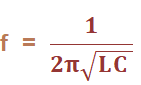
Where, L is the inductance measured in Henry. C is the capacitance measured in Farads The unit of frequency is Hertz. Here, we will discuss the types of LC oscillators, its advantages and disadvantages. There are three types of LC oscillators, which are as follows:
Let's discuss the above three oscillators in detail. Hartley OscillatorPrincipleThe oscillating frequency of the oscillator is determined from the combination of capacitor and inductor in the feedback network. Circuit DiagramThe equivalent circuit of the Hartley oscillator is shown below: 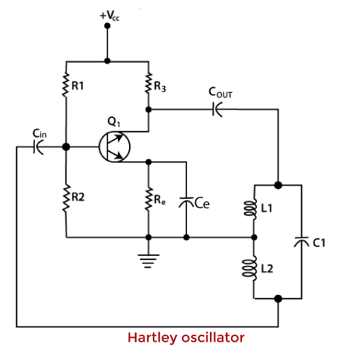
Connection SetupThe feedback circuit of the oscillator comprises of two inductors and one capacitor. The two inductors are connected in series and the capacitor in parallel. The operating frequency range of the Hartley oscillator lies between 20K Hz and 30M Hz. It does not work well at lower frequencies because the inductor value needs to be high. R1 and R2 provide a potential divider bias, and the emitter resistor Re provides thermal stability. He is the bypass capacitor that bypasses the amplified AC signals. If the bypass capacitor is absent, the voltage drop will appear across the Re and may disturb the biasing conditions of the transistor. Cin and Cout are the input and output DC decoupling capacitors, which control the DC voltage and prevent it from reaching any other oscillator stage. The Hartley oscillator is based on the Barkhausen criterion, which states that: A linear system produces sustained oscillations only at frequencies for which the gain of the feedback loop is 1. The phase shift around the loop is zero or an integral multiple of 2pi. The requirement of the oscillator for sustained oscillations or positive feedback is the phase shift of 0 or 360 degrees. It maintains the periodic oscillations of the system. The equivalent frequency is given by: 
Where, Lt is the total inductance or the mutual inductance between the two inductors. It is measured in Henry. WorkingWhen the power supply is switched ON, the transistor starts operating and constitutes the emitter and collector current. The capacitor C1 starts charging when the current from the collector region reaches the circuit in the feedback path of the oscillator. The capacitor C1 becomes fully charged and passes the charge to the inductor. The inductor again passes the charge to the capacitor when it discharges. The charging and discharging process continues that forms the basis of the oscillations. The produced oscillations are fed back to the base of the transistor in the amplified form. The base of the inductor L2 is connected directly to the base of the transistor. The oscillator requires 360 degrees phase shift to maintain the sustained oscillations. The 180 degrees phase shift is provided by the mutual inductance between the two inductors. The transistor provides the other 180 degrees phase shift. Total phase shift = 180 + 180 = 360 degrees Hence, the requirement of sustained oscillations is verified. Hartley oscillator using op-ampThe circuit of the Hartley oscillator using the operational amplifier is shown below: 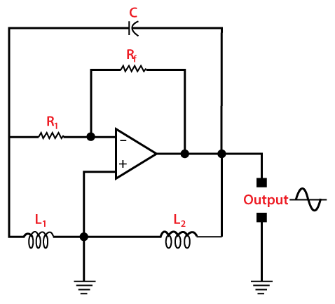
The feedback resistor Rf in the feedback path and the input resistor of the operational amplifier helps to adjust the gain of the oscillator. The gain of the op-amp arranged in inverting mode can be represented as: Av = -Rf/R1 Where, R1 is the input When the input signal is applied to the amplifier's inverting terminal (-), it is known as inverting mode. If the input signal is applied to the amplifier's non-inverting terminal (+), it is known as a non-inverting mode. Here, the oscillator s based on the inverting mode of an amplifier. Rf is the feedback resistor The gain is also expressed as: Av = L2/L1 It is the ratio of the two inductors in the feedback network. The gain can be greater or equal to L2/L1. The stability of the Hartley oscillator is better in the op-amp configuration as compared to the transistor configuration. It is because the gain is less dependent on the circuit elements. The main reason in the variation of the oscillating frequency in LC oscillators arises due to the various circuit elements. If the dependency is reduces, the stability of the op-amp Hartley oscillator automatically improves. Numerical ExampleExample: A Hartley oscillator has the following parameters. C = 2p Farads = 2 x 10-12 Farads F = 1.5M Hz Av = 0.4 Find the two inductances of the oscillator. Solution: Given: C = 2p Farads = 2 x 10-12 Farads F = 1.5M Hz = 1.5 x 10⁶ Hertz Av = 0.4 The voltage gain of the oscillator is the ratio of the inductance of the two coils. It is given by: Av = L2/L1 = 0.4 L1/L2 = 2.5 L1 = 2.5L2 The frequency of oscillations of the Hartley oscillator is given by: 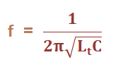
Where, Lt is the total inductance. Lt = L1 + L2 Lt = 1 /C (2πf)2 Lt = 1/ 2 x 10-12(2 x 3.14 x 1.5 x 106)2 Lt = 1/ 2 x 10-12(8.873 x 10¹³) Lt = 1/ 177.472 Lt = 5.63 mH We know, L1 = 2.5L2 Putting the value of L1 in the above equation, we get: Lt = 2.5L2+ L2 Lt = 3.5L2 L2 = Lt/3.5 L2 = 5.63 mH/3.5 L2 = 1.61 mH L1 = 2.5L2 L1 = 4.02 mH Thus, the two inductances of the oscillator are 1.61 mH and 4.02 mH. Colpitts OscillatorPrincipleThe transfer of energy between the two capacitors and inductor in the feedback path of the oscillator forms the basis of the oscillations. Circuit DiagramThe equivalent circuit of the Colpitts Oscillator is shown below: 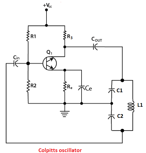
Connection SetupThe Colpitts oscillator's feedback circuit comprises two capacitors and one inductor. A FET (Field Effect transistor) and resistors are used for the circuit realization. The base of the transistor is connected from the junction of the transistor to the capacitor C2 and inductor L1. The two capacitors are connected in series. The frequency of oscillations of the Colpitts oscillator is given by: 
Where, L is the inductance Ct is the total capacitance The equivalent equation of the two capacitors connected in series is represented as: 1/Ct = 1/C1 + 1/C2 Ct = C1C2/(C1 + C2) WorkingWhen the power supply is switched ON, the current flows, the capacitors C1 and C2 start charging. The fully charged capacitors transfers its energy to the inductor connected across it. When the capacitors are fully discharged after transferring all their stored energy, the electrostatic energy gets transferred t the inductor. The inductor starts discharging and transferring its energy to the two capacitors. The cycle of charging and discharging continues, which forms the basis of the oscillations in the circuit. Both the capacitors are connected in opposite phases. The energy from the capacitor C2 gets transferred to the transistor through its junction. The signal at the base and emitter appear in the amplified form. The function of the transistor is to compensate for the energy loss in the circuit. It helps the oscillator to maintain the sustain oscillations. Advantages of Colpitts oscillatorThe performance of the Colpitts oscillator in the high-frequency domain is better than the Hartley oscillator. It is because of the low reactance path the capacitors provide in the feedback circuit. Thus, the Colpitts oscillator can be used in microwave applications. Colpitts oscillator using op-ampThe circuit of the Colpitts oscillator using the operational amplifier is shown below: 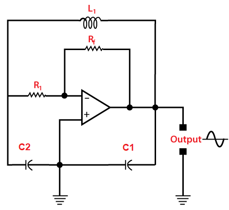
The feedback resistor Rf in the feedback path and the input resistor of the operational amplifier helps to adjust the gain of the oscillator. The gain of the op-amp arranged in inverting mode can be represented as: Av = -Rf/R1 Where, R1 is the input Rf is the feedback resistor The stability of the Colpitts oscillator is better in the op-amp configuration. It is because the gain is less dependent on the circuit elements. The working of the op-amp configuration is similar to that of the transistor one with the frequency equation. Numerical ExampleExample: A Colpitts oscillator has the following parameters. C1 = 1p Farads C2 = 10p Farads L = 10uH Find the operating frequency of the oscillator. Solution: Given: C1 = 1p Farads = 1 x 10-12 Farads C2 = 10p Farads = 10 x 10-12 Farads L = 10uH = 10 x 10-6 Henry The operating frequency is given by: 
Ct = C1C2/(C1 + C2) Ct = 1x 10 /11 Ct = 0.909 pF F = 1/ (2 x 3.14 x (0.909 x 10-12 x10 x 10-6)1/2) F = 1/ (2 x 3.14 x 3.014 x 10-9) F = 0.05281 x 10⁹ Hz F = 52.81M Hz Thus, the operating frequency of the circuit is 52.81M Hz. Clapp OscillatorPrincipleThe combination of three capacitors and an inductor helps the oscillator to generate oscillations. Circuit DiagramThe equivalent circuit of the Clapp Oscillator is shown below: 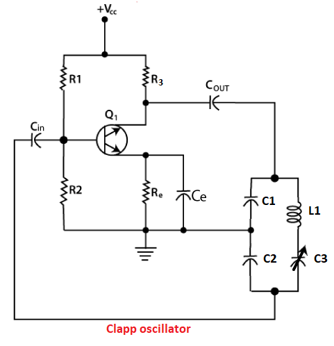
Connection SetupThe feedback path of the circuit consists of the combination of two capacitors, one inductor, and one variable capacitor. Clapp oscillator is a modified version of the Colpitts oscillator. The only difference is the additional variable capacitor in the feedback circuit. It is connected in series to the inductor. The primary purpose of introducing the additional capacitor is to improve the frequency stability of the oscillator. It prevents any disturbance from reaching the capacitors C1 and C2. Due to this, the two capacitors are fixed and the third capacitor is the variable capacitor (C3). The frequency of oscillations is given by: 
Where, L is the inductance Ct is the total capacitance The equivalent equation of the two capacitors connected in series is represented as: 1/Ct = 1/C1 + 1/C2 + 1/C3 The value of C3 is less as compared to C1 and C2. It is made small to reduce the effect on the net effective capacitance. Thus, the equation of frequency of oscillations can also be represented as: 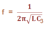
The Clapp oscillator can also work as the variable frequency oscillator due to the presence of the variable capacitor. Numerical ExampleExample: A Clapp oscillator has the following parameters. C1 = 2p Farads C2 = 20p Farads C3 = 0.1p Farads L = 15uH Find the operating frequency of the oscillator. Solution: Given: C1 = 2p Farads = 2 x 10-12 Farads C2 = 20p Farads = 20 x 10-12 Farads C3 = 0.1p Farads = 0.1 x 10⁻¹² Farads L = 15 = 15 x 10-6 Henry The operating frequency of the Colpitts oscillator is given by: 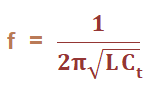
1/Ct = 1/C1 + 1/C2 + 1/C3 1/Ct = 1/10 + 1/20 + 1/0.1 1/Ct = 1/10 + 1/20 + 100/10 1/Ct = (2 + 1 + 200)/20 1/Ct = 203/20 Ct = 20/203 Ct = 0.098p Farads F = 1/ (2 x 3.14 x (15 x 10-6 x 0.098 x 10-12)1/2) F = 1/ (2 x 3.14 x (15 x 10-6 x 0.098 x 10-12)1/2) F = 1/ (2 x 3.14 x 1.215 x 10-9) F = 0.13106 x 10⁹ Hz F = 131.06M Hz Thus, the operating frequency of the Clapp oscillator is 131.06M Hz. Advantages of LC oscillatorsThe advantages of LC oscillators are as follows:
Disadvantages of LC oscillatorsThe disadvantages of LC oscillators are as follows:
Next Topic#
|
 For Videos Join Our Youtube Channel: Join Now
Feedback
- Send your Feedback to [email protected]
Help Others, Please Share


