| |

No-Load and Blocked Rotor TestThe efficiency of small motors can be determined by directly loading them and by measuring the input and output powers. But in the case of large motors, it is difficult to arrange that much load for them. The power loss will be large if we directly test the load. Therefore indirect methods are used to determine the efficiency of 3-phase induction motors. We can perform the following test on the motor to find the efficiency:
No-Load test or Open-Circuit Test:The no-load test of an induction motor is similar to the open-circuit test of a transformer. The motor is not connected from its load, and the rated voltage at the rated frequency is applied to the stator to run the motor without a load. The 2-wattmeter method measures the input power of the system. The voltmeter measures the standard-rated supply voltage and an ammeter measures the no-load current. Since the motor is running at no-load, total power is equal to the constant iron loss, friction and winding losses of the motor. Pconstant = Pi = P1 + P2 = Sum of the two wattmeter readings. 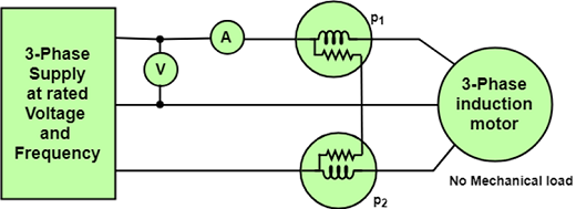
Figure: Circuit diagram for no-load test on a 3-phase induction motor. Since the power factor of the induction motor under a no-load condition is generally less than 0.5, one wattmeter will show a negative reading. Therefore, it is, necessary to reverse the direction of current-coil terminals to take the reading. If Vinl = input line voltage 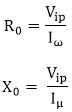
Blocked Rotor or Short-Circuit Test: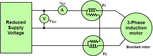
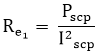
Figure: Circuit diagram for blocked rotor test The blocked rotor test of an induction motor is same as the short-circuit test of a transformer. In this test, the shaft of the motor is connected so that it cannot move and rotor winding is short-circuited. In a slip-ring motor, the rotor winding is short-circuited through slip-rings and in cage motors, the rotor bars are permanently short-circuited. This test is also called the locked-Rotor test. When a reduced voltage at the reduced frequency is applied to the stator through a 3-phase auto-transformer so that full-load current flows in the stator, the following three readings are obtained. 1) The total power input on short-circuits Psc = algebraic sum of the two wattmeter readings. 2) Reading of ammeter Iscl = line current on short circuit. 3) Reading of voltmeter Vscl = Line voltage on the short circuit ∴Psc = √3Vscl cos?Φsc Where cos? ϕc=Power factor on short circuit The equivalent resistance of the motor referred to the statorRe1 is,
Equivalent impedance of the motor referred to the statorZe1 is,
Equivalent reactance of the motor referred to stator 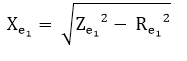
NOTE: The Blocked-Rotor test should be performed under the same conditions of rotor current and frequency that will exist under normal operating conditions. |

 For Videos Join Our Youtube Channel: Join Now
Feedback
- Send your Feedback to [email protected]
Help Others, Please Share


