| |

NOT GateThe NOT gate is the most basic logic gate of all other logic gates. NOT gate is also known as an inverter or an inverting Buffer. NOT gate only has one input and one output. When the input signal is "Low", the output signal is "High" and when the input signal is "High", the output is "Low". The Boolean expression for the NOT gate is as follows: A'=Y When A is not true,then Y is true The standard NOT gate is given a symbol that is shaped like a triangle with a circle at the end, pointing to the right. This circle is known as an "invert bubble" and is used to represent the logical operation of the NOT function in the NOT, NAND and NOR symbols in their output. Logic Design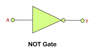
Truth Table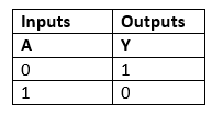
The complement value is generated by the NOT gate. The NOT gate is so-called because when the input signal is 0, the output signal will NOT be 0, Similarly, when the input signal is 1, the output signal will NOT be 1. In the NOT gate, the bubble denotes the single inversion of the output signal. But this bubble can also exist on the gate's input to indicate an active-less input. This reversal of the input signal is not limited only to the NOT gate, but can also be used on any digital circuit or gate, as shown with the operation of inversion, whether it is at the input or output terminals. The easiest way is to think of the bubble as an inverter. Use of Active-low Input Bubble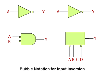
Equivalent GatesThe NOT gate can also be formed with the help of the universal gates, i.e., NAND and NOR. For this, we have to connect both the inputs together to a common input signal. The NOT gate representation of NAND and NOR gate is as follows: 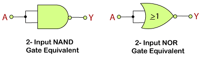
Next TopicNAND Gate
|
 For Videos Join Our Youtube Channel: Join Now
Feedback
- Send your Feedback to [email protected]
Help Others, Please Share


