| |

Open Circuit Test and Short Circuit TestsTo determine the circuit constant, efficiency and regulation of a transformer, without actually loading the transformer, we perform Open-Circuit and Short-Circuit tests. These tests give more accurate result than compared with the fully loaded transformer. And the power consumption in these tests is minimal as compared with the transformer's output on full load. Open Circuit TestThe circuit diagram of the open circuit test for the transformer is shown below: 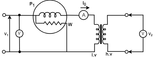
Fig: Open Circuit Test on a Transformer A voltmeter V, an ammeter A, and a wattmeter W are connected in the low voltage (lv) side of transformer. The voltmeter v gives the rated voltage V1 of the primary. A very small current I0, called the no-load current, flows in the primary side because the secondary side is open circuited. The ammeter A, therefore, reads the no-load current I0. The power loss in the transformer occurs due to core loss and a very small I2R loss in the primary. There is no I2R loss in the secondary since it is open and I2 = 0. Since the no-load current I0 is very small, the I2R loss in the primary winding can be neglected. The instrument readings obtained in open circuit test are as follows:
From the above readings we can determine the no-load equivalent circuit: 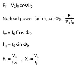
Where X0 is the inductive reactance, IW is the core loss current, Iμ is the magnetizing current. Short Circuit Test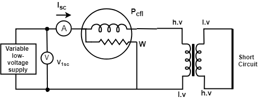
Fig: Short Circuit Test on a Transformer In the short circuit test, usually, the low voltage side is short-circuited by a thick conductor. As we can see that in the figure an ammeter, a voltmeter, and a wattmeter are connected on the high-voltage side. The reason for short-circuiting the low voltage side is as follows:
The high voltage winding is supplied at the reduced voltage from a variable voltage supply. This supply voltage is gradually increased until full-load primary current flows. When the rated full load current flows in the primary winding, then it will also flow in the secondary winding by the transformer action. The readings of the instruments on the short circuit test are as follows:
The equivalent resistance of the transformer referred to primary 
Equivalent impedance referred to primary 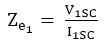
Equivalent reactance referred to primary 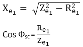
When short circuit test is performed only on one side the equivalent circuit constants referred to another side can also be calculated as follows: 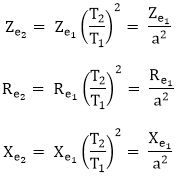
Next TopicThree-Phase Transformer
|
 For Videos Join Our Youtube Channel: Join Now
Feedback
- Send your Feedback to [email protected]
Help Others, Please Share


