What is the full form of PLC
PLC: Programmable Logic Controller
PLC Stands for Programmable Logic Controller. It is an Electronic Device with Electromagnetic Sensors as its foundation. Additionally, they are easily found in Manufacturing facilities and Production companies. By using the logic inside the device, we can solve a problem. The answer is also saved in the data storage, and the output is triggered as soon as possible. Furthermore, PLC is a very powerful automation tool. Numerous programming options are available.
In addition, they only pay attention to those that succeed. When it comes to automation and speed, this device is really useful. The automation software is quite effective. In the market, there are numerous PLCs to choose from. They all have distinct responsibilities. Programming is done by the developers to complete the task. But the PLCs Have A Lot Of Flexibility Too. They are capable of sensing the workplace and adapting to the needs as well. Automation is the future of every industry, and PLC installation is far simpler and superior to other relay systems that are now available in workshops. In a warehouse, the PLC will take over the physical requirements of the workers. Everybody will prefer fast, automatic robots over workers.
History Of Programmable Logic Controller (PLC)
In 1964, Dick Morley created the first PLC. Since then, PLC has completely changed the manufacturing and industrial sectors. PLCs are capable of performing a wide range of tasks, including timing, counting, computing, comparing, and processing various analog signals.
As a result, the logic was typically represented as a series of logical expressions in a Boolean format in early PLCs that could not display the reasoning graphically (akin to Boolean algebra). Ladder logic was utilized increasingly frequently as programming terminals advanced since it was a format that was well-known for electro-mechanical control panels. Though more recent formats like state logic and Function Block diagrams exist, ladder logic remains the most widely used.
PLCs were programmed using proprietary programming panels or special-purpose programming terminals up until about the mid-1990s. These devices frequently contained specific function keys that represented the various logical components of PLC programs. The components of PLC programs were sometimes shown on proprietary programming interfaces as graphic symbols, although it was more common to see contacts, coils, and wires represented in plain ASCII code.
Functions Of Programmable Logic Controller (PLC)
- Data is captured from the machine and the associated devices, such as analog sensor data, and is also supported by human actions such as switching on and off buttons.
- A light may be turned on, a motor may be started, and gadgets may be switched.
- Data input is handled by the central processing unit (CPU), which also runs user-written program logic and generates data.
Applications Of Programmable Logic Controller (PLC)
Automation of industrial control operations uses PLCs. These are employed in the elimination of dangerous chemical substance spraying robots in agricultural fields, the glass washing robot for skyscrapers, and repetitive activities like lift mechanisms and cranes, among others.
Benefits Of Programmable Logic Controller (PLC)
- When compared to the price of real, custom-built control systems, PLCs are less expensive.
- PLCs employ ladder diagram programming.
- A PLC has the capacity to manage far more complicated and large-scale activities. Depending on the application and the user's demands, a PLC can be modified.
Advantages Of Programmable Logic Controller (PLC)
- As programmable logic controllers are adaptable, they can be utilized for a variety of operations, depending on what is needed. It is also simple to install because installing PLC-based control panels takes less time than installing hard-wired relay-based systems.
- Additionally, it is frequently utilized in civil applications like managing traffic lights and elevators as well as in domestic applications like washing machines.
- In many sectors, they are employed to regulate and keep an eye on construction systems and manufacturing processes.
- Any task that requires simple programming, high reliability, and process fault identification has been modified and ruggedized for use with a programmable logic controller.
- In the realm of automation, PLCs are essential since they are a component of a larger SCADA system. According to the process' operational requirements, a PLC can be programmed.
Programmable Logic Controller (PLC) Working
- A cyclic scanning approach known as the scan cycle can be used to explain how a programmable logic controller operates.
- Timekeeping and cycling are initiated by the operating system.
- The CPU begins reading the information from the input module and evaluating the state of each input.
- Relay-ladder logic or another PLC programming language is first started by the CPU before the user or application software.
- The CPU then handles all internal diagnosis and communication functions.
- The data is written into the output module in accordance with the outcomes of the program, updating all outputs.
- As long as the PLC is in run mode, this procedure continues.
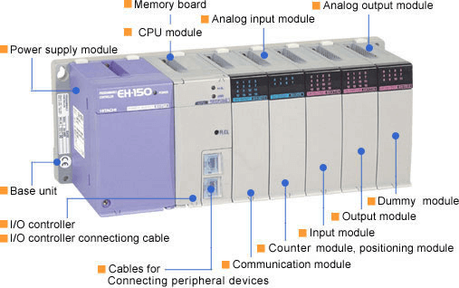
Physical Structure Of Programmable Logic Controller (PLC)
A PLC's architecture is essentially identical to that of a computer.
Depending on the type of production and industry, programmable logic controllers continuously monitor the input values from a variety of input sensing devices (such as an accelerometer, a weight scale, hardwired signals, etc.) and generate the matching output.
A typical PLC block diagram consists of the following five components:
- Rack or chassis- The most crucial component and structural backbone of the system is the PLC rack or chassis. PLCs come in a variety of forms and dimensions. It calls for larger PLC racks when more intricate control systems are required. A fixed I/O pin layout is included with small-sized PLCs. They chose a PLC that is modular in design and can accommodate various I/O module types using a sliding and fit-in method. Inside this rack/chassis will be where all I/O modules will be housed.
- Power Supply Module- The necessary power for the entire PLC system is supplied by this module. It changes the available AC power into the DC power that the CPU and I/O module needs. PLC typically requires a 24V DC supply. Most PLCs do not use an independent power supply.
- Central Processing Unit (CPU)- The CPU gathers input data from sensors, processes it, and then issues the command to the object under control. As was noted in the preceding discussion, voltage signals require a DC power supply. Other electrical components for connecting cables utilized by other devices are present inside the CPU. CPU, which uses an octal or hexagonal microprocessor, is the brain of the PLC.
- Input & Output Module- An input & output module is a special type of PLC module used to interface inputs and outputs. Pushbuttons for starting and stopping the device, switches, etc. are examples of input devices. Electric heaters, valves, relays, etc. are examples of output devices. A microprocessor's input and output devices are connected to it with the aid of an I/O module.
- Communication Interface Module- Intelligent I/O modules are used to move data between CPU and communication networks. These communication modules make it possible to link to other PLCs and computers that are situated far away.
Types Of Programmable Logic Controller
PLCs are divided into two main types.
- Compact PLC- There would be several modules within a single case. Both external I/O cards and I/O modules are fixed in number. Therefore, it lacks the capacity to increase the modules. The manufacturer would determine every input and output.
- Modular PLC- The term "Modular PLC" refers to the PLC type that allows for multiple expansions using "modules." You can add more I/O components. Each component operates separately from the others, making it simpler to use.
Programmable Logic Controller (PLC) Programming
Designing and implementing concepts for your specific use case is crucial when using a PLC. We first need to learn more about the specifics of PLC programming in order to accomplish this. A PLC program is made up of a series of textual or graphic instructions that represent the logic underlying the process the PLC is controlling.
PLC programming languages fall under two broad categories, each of which is further subdivided into numerous subtypes.
Textual Language
- Instruction list
- Structured text
Graphical Form
- Ladder Diagrams (LD) (i.e. Ladder Logic)
- Function Block Diagram (FBD)
- Sequential Function Chart (SFC)
Programmable Logic Controller (PLC) Programming Examples
- If a pump is running and the pressure is adequate or the lamp test switch is closed, a signal lamp must be turned on. In this case, inputs from both the pump and the pressure sensor are necessary if the light should provide an output. And logic gates are so utilized.
- It is necessary to output a lamp-on signal regardless of whether there is a signal from the AND system, hence OR logic is employed for the test input condition. The ladder diagram's use of the END or RET instruction indicates that the PLC has finished running the program.
- A valve that should be turned on to lift a load when a pump is running and either the lift switch is turned on or a switch that indicates the load hasn't been lifted yet and is at the bottom of its lift channel is turned on.
- When there are two switches, OR logic is utilized, and when there are two switches and a pump, AND logic is used. Only when both switches are activated and the pump is ON will the valve be opened.
|

 For Videos Join Our Youtube Channel: Join Now


