Polyline command in Solid works
A drawing element called a Polyline is made up of linked Lines or linked arc segments. Polylines may be made with fill settings and segments of various widths. A linear segment is the standard segment type for a Polyline.
You may change a Polyline using a number of techniques after you create it.
- Vertices can be added, removed, or moved using grip points. Furthermore, you may change straight segments into arcs and the opposite.
- Change the width and taper of the whole Polyline by using the Edit Polyline command. In addition, you may shut an open Polyline or open a closed Polyline.
Note: Several options for altering Polylines are gathered in the Properties panel.
To build Polylines:
- Select Polyline under Draw (or type Polyline).
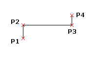
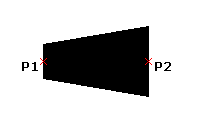
- Set the beginning of the first Polyline segment in the graphics area.
- Give alternatives for the following section:
- The segment type is changed to an arc.
The Clockwise option determines the arc's direction (see Specifying Units and Precision). When defining an angle, hold down the Ctrl key to draw the arc in the opposite direction.
- Angle: An arc segment's angle relative to the initial point serves to define it.
- An arc segment is defined by its centre.
- The direction of a tangent to the initial point defines an arc segment.
- Describes the width symmetrically with respect to the segment end point.
- the segment type is changed to Line.
- defines a segment of an arc based on its radius.
- To point through. Names the location across which the following arc section will travel.
- reverses a previous section.
- Creates a thick line or arc segment by specifying the start and end width of the subsequent Polyline segment.
- Indicate where the section ends.
- Do one:
- Each subsequent section should be specified using steps 3 and 4.
- Select the Close option to create a closed Polyline after entering at least two segments, or just press Enter.
While creating a Polyline, the following steps must be followed:
- Select Polyline under Draw (or type Polyline).
- Set the beginning of the first Polyline segment in the graphics area.
- Add a width specification.
- Enter the segment's start width here.
- Enter the segment's end width here.
- Indicate where the section ends.
Up until you select a different end width by supplying the Width option, the end width you specify applies to every future Polyline segment.
To define a Polyline arc segment from three points:
- Select Polyline under Draw (or type Polyline).
- Set the beginning of the first Polyline segment in the graphics area.
- Give the Arc option a name.
- Indicate the Through point choice.
- Indicate the arcs through point and end point.
To specify a Polyline arc segment starting at a center point:
- Select Polyline under Draw (or type Polyline).
- Set the beginning of the first Polyline segment in the graphics area.
- Give the Arc option a name.
- Indicate the Center selection.
- Indicate the arc's centre.
- Indicate the arc's end point or a choice.
- Give an angle.
- Give the chord's length.
From a radius and three points, one may specify an arc segment of a Polyline:
- Select Polyline under Draw (or type Polyline).
- Set the beginning of the first Polyline segment in the graphics area.
- Give the Arc option a name.
- Indicate the Radius choice.
- Set the endpoint and arc radius.
Using a radius, angle, chord direction, and two locations, one can define an arc segment of a Polyline as follows:
- Select Polyline under Draw (or type Polyline).
- Set the beginning of the first Polyline segment in the graphics area.
- Give the Arc option a name.
- Indicate the Radius choice.
- Choose the arc's radius.
- Indicate the Angle choice.
- Name the included angle.
- Enter the chord direction and arc end point in the graphics section.
In order to specify a Polyline arc segment from an angle from the start point and include an end point:
- Select Polyline under Draw (or type Polyline).
- Set the beginning of the first Polyline segment in the graphics area.
- Give the Arc option a name.
- Indicate the Angle choice.
- Give the angle a positive or negative value.
- Indicate the arc's end point or a choice:
- It allows you to choose the arc's centre.
- It allows you to choose the chord direction and radius.
In order to specify a Polyline arc segment from a tangent direction from the start point and an end point:
- Select Polyline under Draw (or type Polyline).
- Set the beginning of the first Polyline segment in the graphics area.
- Give the Arc option a name.
- Indicate the Direction choice.
- Indicate the tangent direction for the arc's start point and end point in the graphics area.
| 
 For Videos Join Our Youtube Channel: Join Now


