| |

RC Phase shift oscillatorThe phase shift oscillators are linear electronic oscillators that produce the sinusoidal wave output. A phase shift oscillator consists of an input amplifier and a feedback path, as shown below: 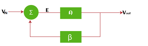
It is a simple diagram of a phase shift oscillator. RC oscillators have R and C as the phase shift network in the feedback path, which is fed back to the input. RC phase shift oscillator is a feedback oscillator with phase shift present as the feedback factor. RC signifies a combination of R (resistor) and C (capacitor) that produces the phase shift in the oscillator output. It is generally used at the audio frequency range. 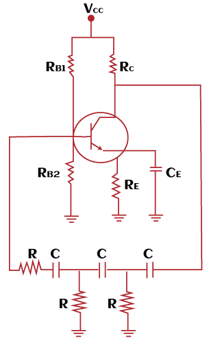
The components of the RC oscillators are inverting amplifiers (transistors and operational amplifiers), resistors, and capacitors in the ladder form. The inverting amplifiers have various advantages, such as finite gain, and finite input impedance. The amplifiers provide a phase shift of 180 degrees and the phase shift network also provides a phase shift of 180. The RC oscillator utilizes the phase shift provided by both components. Phase shift = 180 (amplifiers) + 180 (feedback) Phase shift = 360 degrees Phase shift = 360 degrees = 0 degrees Thus, it helps the oscillator to provide positive feedback. The frequency of oscillations of an RC phase shift oscillator is: Fo = 1/[2? (6 + 4 RC/R)] We can also consider an RC phase oscillator using FET (Field Effect Transistor) instead of an amplifier, as shown below: 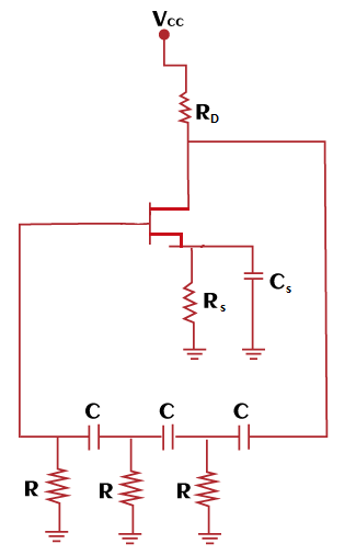
Here, Rs and Cs are the resistor and capacitor connected across the source terminal of the FET. The frequency of oscillations of a FET RC phase shift oscillator is given by: 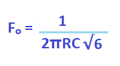
It can also be represented as: 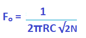
Where, N specifies the number of RC stages connected in the feedback phase network. 2N is directly substituted as 6 because there are fixed 3 of RC stages. In the case of RC stages > 3, the value of N changes. The frequency value can be changed by varying the value of resistors or capacitors. The phase angle of an RC circuit can be represented as: A = tan-1(XC/R) Where, R is the resistance XC = 1/2?fC F is the frequency C is the capacitance A single RC network produces a phase shift of maximum 90 degrees. But, an RC phase shift oscillator requires atleast 180 degrees phase shift from the feedback. Hence, two or more than two RC networks are connected in the feedback to produce the desired phase shift. Let's discuss how three capacitors and two resistors produce a phase shift of 180 degrees. Minimum phase shift by each RC network = 60 degrees For 180 degrees, the required RC networks are 180/60 = 3 Thus, three RC networks are connected in the feedback path to produce 180 degree phase shift. Op-amp implementation of the phase shift oscillatorThe implementation of the RC phase oscillator using the operational amplifier is shown below: 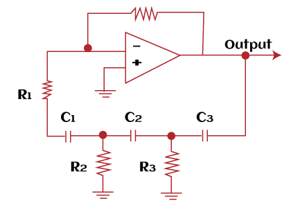
It has three capacitors and four resistors. If we assume the value of resistors R1 = R2 = R3 = R and capacitors C1 = C2 = C3 = C, the calculations becomes easy. The frequency of oscillations can be represented as:
The oscillation criterion is: Rfb = 29. R Where, Rfb is the feedback resistor The above condition is assumed by considering all resistors equal to R except the resistor in negative feedback. Otherwise, the calculations are quite complex. The frequency of oscillations can now be represented as: Fo = 1/2π (R2R3 (C1C2 + C1C3 + C2C3) + R1R3 (C1C2 + C1C3) + R1R2C1C2)1/2 The single op-amps circuits require a high gain (around 30) to balance the ladder network of resistors and capacitors connected in the feedback. The high gain helps it to maintain the oscillations. If the RC network is stable, a gain of around 10 will be sufficient for the oscillator. We can also insert a buffer to each RC network in the circuit. It prevents loading and does not disturb the oscillations. AdvantagesThe advantages of phase shift oscillator are as follows:
The above advantages allow the RC phase shift oscillators in various applications, such as musical instruments, and GPS (Global Positioning System) units. DisadvantagesThe disadvantages of phase shift oscillator are as follows:
Numerical ExamplesLet's discuss an example based on the RC phase shift oscillators. Example: In the FET (Field Effect Transistor) phase shift oscillator, R1 = R2 = R3 = 2M Ohms and C1 = C2 = C3 = 80 p Farads. Fid the frequency at which the circuit will oscillate. Solution: Given: R1 = R2 = R3 = R = 2M Ohms = 2 x 10⁶ Ohms C1 = C2 = C3 = C = 34 pF = 80 x 10-12 Farads The frequency of oscillations can be calculated using the formula given by:
Fo = 106 / (2 x 3.1415 x 2 x 106 x 80 x 10-12 x 2.449) Fo = 106/ 2461.93 Fo = 406.18 Hz Thus, the frequency of oscillations is 406.18 Hz.
Next TopicWien bridge oscillator
|
 For Videos Join Our Youtube Channel: Join Now
Feedback
- Send your Feedback to [email protected]
Help Others, Please Share


