| |

Resistance DefinitionElectrical Resistance is a property of a material to obstruct the flow of current. Suppose there is a material it can either be a conductor or a semiconductor. There is a potential difference (V) across both ends, and I amount of current is flowing in the material from the positive (+) terminal to the negative (-) terminal. So, the Resistance of this material is always given by the formula: [ R = V / I]
The electrons inside the conductor move from the negative terminal to the positive terminal, opposite to the current flow; during this movement, electrons collide with the positively charged atoms or positively charged kernels present in the conductor, which obstructs the flow of the current. Note: The flow of electrons results in the generation of current.I = Vd x e x n x A --- (1)
It is calculated as: Vd = e x V x 𝛕 / m x l ---(2)
Putting the value of equation 2 in equation 1, we get, I = (e x V x 𝛕 / m x l) x e x n x A V / I = m x l / n x e2 x A x 𝛕 R = V / I = m x l / n x e2 x A x 𝛕 Except for l and A rest of the values on the right-hand side are constant for a conductor at a given temperature. These constant values are expressed in a single variable called rho (p). Rho denotes the resistivity of the material. It depends upon the material used in the experiment and the temperature and does not depend on the shape and size of the conductor. The SI unit of the resistivity is the ohm meter. R = (p x l) / A Practice QuestionQuestion 1. A wire of length l has Resistance R. This wire is stretched to twice its original length. Find the new Resistance of the wire. Solution: Initial Resistance of the wire (R) = p x l / A After stretching the wire twice, its length becomes twice its original length, and the area of the cross-section is reduced to half with the same resistivity (p). new l = l' = 2l new A = A' = A / 2 So, new resistance let say R' = p (2l) / (A / 2) R' = 4 x p x l / A R' = 4 x R Hence, the new Resistance is four times the original Resistance. Question 2. A wire of length l has resistance R. This wire is compressed to half of its original length. Find the new Resistance of the wire. Solution: Initial Resistance of the wire (R) = p x l / A After compressing the wire, its length becomes half of its original length, and the area of the cross-section becomes double with the same resistivity (p). new l = l' = l / 2 new A = A' = 2A So, new resistance let say R' = p (l / 2) / (2A) R' = p x l / 4A R' = R / 4 Hence, the new Resistance is one-fourth of the original Resistance. The general formula to solve problems in which the conductor or wire is stretched or compressed, or beaten: [R' = n2 x R] Where,
n = lf / li lf is the final length, and li is the initial length. For example, if n = 2 R' = (22) x R R' = 4 x R if n = 1 / 2 R' = (1 / 2)2 x R R' = (1 / 4) x R R' = R / 4 Question3. A wire of Resistance 3 ohm is stretched 10 times to its original length. Find the new Resistance. Given that R = 3 ohm and n = 10 Using R' = n2 x R R' = 10 x 10 x 3 Therefore R' = 300 ohms. Resistance of Different Shaped Conductors
Using R = (p x l) / A Where l = a and A = area of one phase of the cube = a x a = a2. R = p x a / a x a R = p / a 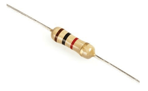
A resistor is anything in which current can flow. A simple conductor can also be a resistor. Resistance is the conductor's property to oppose the flow of current. This is a resistor used in real-life circuits. Resistors are often color-coded to indicate their resistance value and tolerance. The color code is typically a series of colored bands that are painted on the outer covering of the resistor. The number of bands can vary, but resistors commonly have four or five bands. The first and second bands indicate the first two digits of the resistance value. The third band is the multiplier band, indicating the number of zeros to add to the first two digits. The fourth band is the tolerance band, indicating the accuracy of the resistance value. Some 5-band resistors also have a 5th band, which indicates the resistor's reliability. A Quick Guide to the Color Codes
The Multiplier Band's Color Codes are:
The Tolerance Band's Color Codes are:
The Reliability Band's Color Codes are:
It is important to note that the color codes may vary depending on the manufacturer, so it's always best to check the specifications of a specific resistor before interpreting the color code. Solved Examples of Color Coding of ResistorsExample 1: A resistor has four color bands: brown, black, red, and gold. Find its resistance value. Solution: The first band is brown and represents the first digit 1. The second band is black and represents the second digit 0. So, the first two digits of the resistance value are 10. The third band is red and represents the multiplier x100. Therefore, the resistance value is 10 x 100 = 1000 ohms or 1k ohms. The fourth band is gold and represents a tolerance of ±5%. Example 2: A resistor has five color bands: brown, yellow, orange, gold, and brown. Find its resistance value. Solution: The first band is brown and represents the first digit 1. The second band is yellow and represents the second digit, 4. So, the first two digits of the resistance value are 14. The third band is orange and represents the multiplier x1,000. Therefore, the resistance value is 14 x 1,000 = 14000 ohms or 14k ohms. The fourth band is gold and represents a tolerance of ±5%. The fifth band is brown and represents the reliability of low. Example 3: A resistor has four color bands: yellow, gray, red, and silver. Find its resistance value. Solution: The first band is yellow and represents the first digit, 4. The second band is gray and represents the second digit 8. So, the first two digits of the resistance value are 48. The third band is red and represents the multiplier x100. Therefore, the resistance value is 48 x 100 = 4800 ohms or 4.8k ohms. The fourth band is silver and represents a tolerance of ±10%. It is very important to remember that the color codes for resistors may vary depending on the manufacturer, so it is always best to check the specifications of a specific resistor before interpreting the color code. There are several ways that resistors can be combined in circuit diagrams to create different types of circuits. Here are a few examples:
Out of these four, only series and parallel combinations are important. 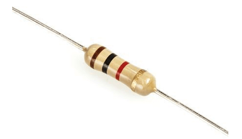
It is important to note that a circuit's actual resistance value depends on the resistors' specific values and the circuit's layout. Here are some examples of solving circuit diagrams that involve series and parallel combinations of resistors: Series CombinationExample 1: A circuit contains three resistors R1 = 2 ohms, R2 = 3 ohms, and R3 = 4 ohms connected in series. Find the total Resistance. Solution: The total Resistance of a series combination is equal to the sum of the individual resistances. R_total = R1 + R2 + R3 = 2 ohms + 3 ohms + 4 ohms = 9 ohms Example 2: A circuit contains two resistors R1 = 5 ohms and R2 = 10 ohms connected in series. Find the total Resistance. Solution: R_total = R1 + R2 = 5 ohms + 10 ohms = 15 ohms Parallel CombinationExample 1: A circuit contains three resistors R1 = 2 ohms, R2 = 3 ohms, and R3 = 4 ohms connected in parallel. Find the total Resistance. Solution: The total Resistance of a parallel combination is equal to the reciprocal of the sum of the reciprocals of the individual resistances. 1/R_total = 1/R1 + 1/R2 + 1/R3 = 1/2 + 1/3 + 1/4 = 13/12 ohms R_total = 12/13 ohms Example 2: A circuit contains two resistors, R1 = 5 ohms and R2 = 10 ohms, connected in parallel. Find the total Resistance. Solution: 1/R_total = 1/R1 + 1/R2 = 1/5 + 1/10 = 3/10 ohms R_total = 10/3 ohms It is important to note that the above examples show the circuit's total Resistance, which opposes the current flow in the circuit. Wheatstone Bridge CircuitExample 1: A Wheatstone bridge circuit contains four resistors R1 = 10 ohms, R2 = 12 ohms, R3 = 15 ohms, and R4. The voltage source is V = 12V. Find the unknown resistance R4. Solution: The basic principle of a Wheatstone bridge is to have the same current flowing through R2 and R4 and make the voltage across R2 and R4 equal to the voltage across R1 and R3. This will make the voltage across the two output terminals zero. Let's assume that the current flowing through the circuit is I. Voltage across R1 = I * R1 Voltage across R3 = I * R3 Voltage across R2 = I * R2 Voltage across R4 = I * R4 As per the basic principle of the Wheatstone bridge, I * R2 = I * R4 and I * R1 = I * R3 R2/R4 = R1/R3 Given R1 = 10 ohms, R2 = 12 ohms, R3 = 15 ohms. R4 = R3 * R2 / R1 = 15 * 12 / 10 = 18 ohms. Therefore, the unknown resistance R4 is 18 ohms. Example 2: A Wheatstone bridge circuit contains four resistors R1 = 10 ohms, R2 = 12 ohms, R3 = unknown Resistance, and R4 = 20 ohms. The voltage source is V = 10V. Find the unknown resistance R3. Solution: Let's assume that the current flowing through the circuit is I. As per the basic principle of the Wheatstone bridge, I * R2 = I * R4 and I * R1 = I * R3 R2/R4 = R1/R3 Given R1 = 10 ohms, R2 = 12 ohms, R4 = 20 ohms and V = 10V R3 = R1 * R4 / R2 = 10 * 20 / 12 = 16.67 ohms It is important to note that in a Wheatstone bridge, the current flowing through the circuit is the same in all the resistors and the voltage across R2 and R4 is equal to the voltage across R1 and R3. This makes the voltage across the two output terminals zero.
Next TopicSentence Definition
|
 For Videos Join Our Youtube Channel: Join Now
Feedback
- Send your Feedback to [email protected]
Help Others, Please Share


