| |

RTL VerilogIn the digital circuit design, register-transfer level (RTL) is a design abstraction which models a synchronous digital circuit in terms of the data flow between hardware register, and the logical operations performed on those signals. Register-transfer-level abstraction is used in HDL to create high-level representations of a circuit, from which lower-level representations and ultimately actual wiring can be derived. Design at the RTL level is a typical practice in modern digital design. 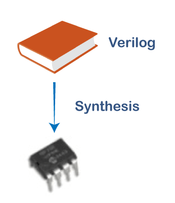
A synchronous circuit consists of two elements, such as:
For example, a simple synchronous circuit is shown in the below image. The inverter is connected from the output Q to the register's input D to create a circuit. It changes its state on each rising edge of the CLK. In this circuit, the combinational logic consists of the inverter. 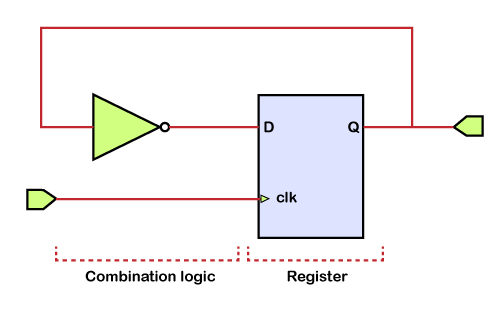
While designing digital integrated circuits with a hardware description language, the designs are usually arranged at a higher level of abstraction than the transistor level or logic gate level. In HDLs, the designer declares the registers, which roughly correspond to variables in the programming languages and describes the combinational logic by using constructs such as if-then-else and arithmetic operations. This level is called the register-transfer level or RTL. The term RTL focuses on describing the flow of signals between registers. This description can usually be directly translated into an equivalent hardware implementation file using an EDA tool for synthesis. The synthesis tool also performs logic optimization. At the register-transfer level, some types of circuits can be recognized. If there is a cyclic path of logic from a register's output to its input, then the circuit is called a state machine or sequential logic. If there are logic paths from a register to another without a cycle, then it is called a pipeline. RTL Circuit Design CycleRTL is used in the logic design phase of the integrated circuit design cycle. An RTL description is converted into a gate-level description of the circuit by a logic synthesis tool. The synthesis results are then used by placement and routing tools to create a physical layout. Logic simulation tools may use a design's RTL description to verify its correctness. Power Estimation TechniqueThe most accurate power analysis tools are available for the circuit level, but even with a switch rather than device-level modelling, tools at the circuit level have disadvantages. They are either too slow or require too much memory. The majorities of these are simulators like SPICE and used by the designers for many years as performance analysis tools Due to these disadvantages, gate-level power estimation tools have begun to gain some acceptance where faster, probabilistic techniques have begun to gain a foothold. But it also has its trade-off as speedup is achieved on the cost of accuracy, especially in the presence of correlated signals. Over the years, it has been realized that the low power design cannot come from the circuit- and gate-level optimizations. In contrast, system, architecture, and algorithm optimizations tend to have the largest impact on power consumption. Therefore, there has been a shift in the tool developers' incline towards high-level analysis and optimization tools for power. Gate Equivalent TechniqueIt is a technique based on the concept of gate equivalents. The complexity of chip architecture can be described approximately in terms of gate equivalents, where the equivalent gate count specifies the average number of reference gates that are required to implement the particular function. The total power required for the particular function is estimated by multiplying the approximated gate equivalents with the average power consumed per gate. The reference gate can be any gate, e.g., 2-input NAND gate. This technique is distributed in the following types, such as: 1. Class Independent Power Modeling: It is a technique which tries to estimate chip area, speed, and power dissipation based on information about the complexity of the design in terms of gate equivalents. The functionality is divided among different blocks, but no distinction is made about the functionality of the blocks. It is class independent. This technique is used by the Chip Estimation System (CES). This technique completes the following steps: Step 1: Identify the functional blocks such as counters, decoders, multipliers, memories, etc. Step 2: Assign a complexity in terms of Gate Equivalents. The number of GE's for each unit type are either taken directly as an input from the user or fed from a library. 2. Class Depedent Power Modeling: This approach is slightly better than the previous approach as it takes into account customized estimation techniques to the different types of functional blocks. Therefore it is trying to increase the modelling accuracy, which wasn't in the case of previous techniques such as logic, memory, interconnects, and clocks. The power estimation is done in a very similar manner to the independent case. The basic switching energy is based on a three-input AND gate and is calculated from technology parameters, e.g., gate width, tox, and metal width provided by the user. Disadvantages This approach also has the following disadvantages, such as:
Pre-characterized Cell Libraries TechniqueThis technique further customizes the power estimation of various functional blocks by having a separate power model for logic, memory, and interconnects. These suggest a Power Factor Approximation (PFA) method for individually characterizing an entire library of functional blocks such as multipliers, adders, etc. instead of a single gate-equivalent model for "logic" blocks. Advantages Pre-characterized cell libraries technique provides the following advantages:
Next TopicScalar & Vector
|
 For Videos Join Our Youtube Channel: Join Now
Feedback
- Send your Feedback to [email protected]
Help Others, Please Share


