| |

IntroductionIn our previous sections, we learned about combinational circuit and their working. The combinational circuits have set of outputs, which depends only on the present combination of inputs. Below is the block diagram of the synchronous logic circuit. 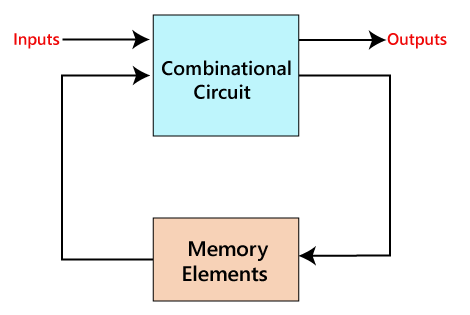
The sequential circuit is a special type of circuit that has a series of inputs and outputs. The outputs of the sequential circuits depend on both the combination of present inputs and previous outputs. The previous output is treated as the present state. So, the sequential circuit contains the combinational circuit and its memory storage elements. A sequential circuit doesn't need to always contain a combinational circuit. So, the sequential circuit can contain only the memory element. Difference between the combinational circuits and sequential circuits are given below:
Types of Sequential CircuitsAsynchronous sequential circuitsThe clock signals are not used by the Asynchronous sequential circuits. The asynchronous circuit is operated through the pulses. So, the changes in the input can change the state of the circuit. The asynchronous circuits do not use clock pulses. The internal state is changed when the input variable is changed. The un-clocked flip-flops or time-delayed are the memory elements of asynchronous sequential circuits. The asynchronous sequential circuit is similar to the combinational circuits with feedback. Synchronous sequential circuitsIn synchronous sequential circuits, synchronization of the memory element's state is done by the clock signal. The output is stored in either flip-flops or latches(memory devices). The synchronization of the outputs is done with either only negative edges of the clock signal or only positive edges. Clock Signal and TriggeringClock signalA clock signal is a periodic signal in which ON time and OFF time need not be the same. When ON time and OFF time of the clock signal are the same, a square wave is used to represent the clock signal. Below is a diagram which represents the clock signal: 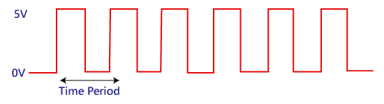
A clock signal is considered as the square wave. Sometimes, the signal stays at logic, either high 5V or low 0V, to an equal amount of time. It repeats with a certain time period, which will be equal to twice the 'ON time' or 'OFF time'. Types of TriggeringThese are two types of triggering in sequential circuits: Level triggeringThe logic High and logic Low are the two levels in the clock signal. In level triggering, when the clock pulse is at a particular level, only then the circuit is activated. There are the following types of level triggering: Positive level triggeringIn a positive level triggering, the signal with Logic High occurs. So, in this triggering, the circuit is operated with such type of clock signal. Below is the diagram of positive level triggering: 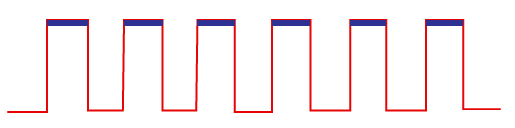
Negative level triggeringIn negative level triggering, the signal with Logic Low occurs. So, in this triggering, the circuit is operated with such type of clock signal. Below is the diagram of Negative level triggering: 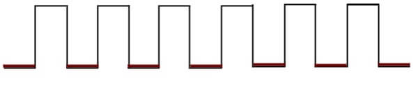
Edge triggeringIn clock signal of edge triggering, two types of transitions occur, i.e., transition either from Logic Low to Logic High or Logic High to Logic Low. Based on the transitions of the clock signal, there are the following types of edge triggering: Positive edge triggeringThe transition from Logic Low to Logic High occurs in the clock signal of positive edge triggering. So, in positive edge triggering, the circuit is operated with such type of clock signal. The diagram of positive edge triggering is given below. 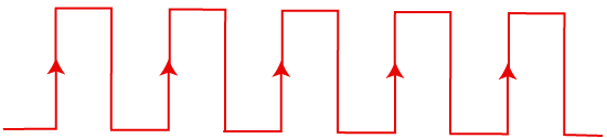
Negative edge triggeringThe transition from Logic High to Logic low occurs in the clock signal of negative edge triggering. So, in negative edge triggering, the circuit is operated with such type of clock signal. The diagram of negative edge triggering is given below. 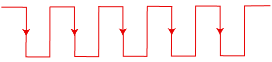
Next TopicBasics of Flip Flop
|
 For Videos Join Our Youtube Channel: Join Now
Feedback
- Send your Feedback to [email protected]
Help Others, Please Share


