Shell command in Solid Works
The shell tool builds thin-walled features on the remaining faces while hollowing out the selected faces and leaving the other faces open.
You can shell a solid part to make a closed, hollow model if you don't choose any faces on the model. Additionally, you may shell a model with different thicknesses.
The Property Manager's Error Diagnostics section appears to assist you in identifying the issue if the Shell tool has trouble shelling a model.
Contents
uniform-thickness shell
Shell with Multiple Face Thicknesses
For various faces, you may design shell features with various wall thicknesses. A default thickness may be specified for the remaining faces after faces are removed, and variable thicknesses can be defined for faces you choose from the remaining faces.
Feature Diagnostics for Shell
The shell feature contains tools to assist you in figuring out why the shell feature failed and shows error messages. Error Diagnostics is a diagnostic tool that can be found in Shell Property Manager.
uniform-thickness shell
To get a consistent thickness in a shell feature:
- In the Features toolbar, choose Shell, or select Insert > Features > Shell.
- You may build an equation in the Property Manager's Parameters section by inserting the equal sign (=) and choosing from a drop-down selection of global variables, functions, and file properties in fields that accept numeric input. In PropertyManagers, see Equations Directly Input.
- Set Thickness to determine the faces' thickness.
- In the graphics box for Faces to delete, choose one or more faces.
A box called Solid Body select face planar.png emerges when you shell a multibody component. The box vanishes once you choose a face or a body to delete.
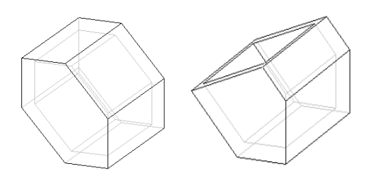
The solid's interior is hollowed out by the shell feature, leaving a shell with a predetermined wall thickness. Surfaces to be removed from the shell might be specified. Without choosing a surface to remove, a closed shell is produced, leaving the whole interior of the body hollow and with no access to the interior. The required cuts or holes can then be added to create the correct geometry in this situation.
By inputting a negative value or selecting the Shell tab, you may change the thickness side such that the thickness of the shell is added to the exterior of the body.
You may choose surfaces and give them a varying thickness when defining a shell. For each of these surfaces, you may define separate thickness values. For these surfaces, you cannot, however, enter negative thickness values or reverse the thickness direction. The default thickness of the shell determines the thickness side.
You may choose the nearby tangent surfaces using the shell feature. The surfaces that are tangent to their adjoining surface at one or more boundaries can then be removed or offset (independently or with a different thickness). A typical capping surface is built to fill the space at the tangent edge, where the shell offset separates.
By indicating the surfaces in the Exclude surfaces collection, you may also prevent one or more surfaces from being shelled. This method is known as partial shelling. Surfaces with neighboring tangent surfaces may also be disregarded. Geometry that is normal to the surfaces listed in the Exclude surfaces collection cannot be shelled by the system.
The body geometry that was composed of solid features before to the creation of the shell feature gets hollowed out when the shell is produced. As a result, while using shell, the sequence in which features are created is crucial. View the illustration in the links.
You may shell every body in the model or just a few.
Click Model >  Shell to access the shell function. Shell to access the shell function.
Commands
- Thickness
- Thickness box: Sets the default shell thickness value;
- Flips the Shell feature's orientation.
Tabs
- References
- Shells geometry from all the model's bodies is provided by the "Bodies to shell" option.
- Geometry for the specified bodies' shells. Unless another body is chosen, the default body is chosen.
- Selects the body from which geometry is subtracted using the bodies collector.
- Remove surfaces-Shows the surfaces that need to be removed. If none of the surfaces are chosen, a closed shell is produced, with the body's interior hollowed out and with no entrance.
- Non-default thickness-Shows surfaces on which a different thickness can be applied. You can provide a unique thickness value for each surface that is part of this collection.
- Options
- Displays one or more surfaces to exclude from the shell under "Exclude surfaces." The entire body gets shelled if no surface is chosen to be excluded.
- Details: Adds or removes surfaces by opening the Surface Sets dialogue box.
- When using the Shell user interface to open the Surface Sets dialogue box, you are unable to pick patchwork surfaces.
- Exposes extension
- Extending the inner surfaces of the shell feature creates a cover over them.
- Extend excluded surfaces-Forms a cover over the shell feature's prohibited surfaces.
- impede the shell's penetration of solid objects by
- Concave corners: These corners prevent the shell from piercing the solid.
- Convex corners-Prevents the shell from piercing the solid when they are convex.
- Properties
- Name box-Names a feature; displays component information in a browser; sets a feature's name.
Menu shortcuts
To access the commands on the shortcut menu, right-click the graphics window.
- Remove Surfaces-Starts the collector for removing surfaces.
- Non-Default Thickness-Activates the collector for non-default thickness.
- Exclude Surfaces-Starts the collector for excluding surfaces.
- Select bodies-Uses the body collector's selection feature.
- Clear: This option clears the current collector.
- Turns the shell side with a flip.
To open the shortcut menu, right-click the handle or value associated with the O THICK label.
- Turns the shell side with a flip.
- You may access the shortcut menu by performing a right-click on the handle or value associated with a THICK label.
- Remove-Removes the current surface from the thickness collector that is not the default.
- To open the shortcut menu, right-click the label Individual Surfaces.
- Remove Set-Removes the chosen surface or surfaces from the collection of Exclude surfaces.
- Solid Surfaces: Builds the surface set and includes all solid surfaces in it.
- To access the shortcut menu commands, right-click the label for the Seed and Boundary Surfaces.
- Activate Set-Activates the chosen set so that surfaces can be added to or removed from the set.
- Remove Set-Eliminates the border and seed surface sets from the surfaces collector for excluding.
Making a Shell Feature
- Select Shell under Model. Opens the Shell tab.
A default thickness is applied to the interior of all of the default body's surfaces if it serves as a reliable reference for the shell feature, resulting in a closed shell. The geometry preview is shown.
- Click the References tab and pick one of the following options to choose the bodies from which geometry is removed:
- Select All to access the shell shape for everybody in the model.
- From chosen bodies, to shell geometry
- Choose Selected.
- Click the body collector, then choose the bodies you want to use for the shell geometry.
- To remove surfaces, choose one or more surfaces and click the Remove surfaces collector on the References tab. Before using the shell tool, you may also choose which surfaces to delete.
- Choose one of the following options to change the shell's thickness:
- Enter a value in the box under Thickness on the Shell tab.
- Drag the graphics window's thickness handle.
- In the graphics window, double-click the thickness value and enter a new value.
- Click the Shell tab to flip the shell inside or outside the body.
- To choose a different thickness for particular surfaces:
- Click the Non-default thickness collector on the References tab and then choose surfaces.
- Define a new thickness value for each chosen surface using one of the following methods:
- In the Non-default thickness collector, enter a new value.
- Drag the graphics window's thickness handle.
- In the graphics window, double-click the thickness value and enter a new value.
- To prevent surfaces from getting shelled, click the Exclude surfaces collection under the Options tab and choose one or more surfaces.
- Press
 OK. OK.
Limitations on the Development of Shell Features
Note the following limitations on constructing shell features:
- The shell feature may be mathematically undefinable if the body contains a corner between more than three surfaces. The issue area is indicated in this instance. A surface that has been entirely revolved is ineligible for removal, and surfaces that cross an edge must do so at angles that are less than 180 degrees with respect to the solid geometry.
- Any sculpted surface can be chosen as the surface to be removed as long as this requirement is satisfied.
- Surfaces that have been chosen in one collector cannot be chosen in another. For instance, you cannot pick the same surface in the Non-default thickness collector or the Exclude surfaces collector if you select it in the Remove surfaces collector.
| 
 For Videos Join Our Youtube Channel: Join Now


