Data Flow DiagramsA Data Flow Diagram (DFD) is a traditional visual representation of the information flows within a system. A neat and clear DFD can depict the right amount of the system requirement graphically. It can be manual, automated, or a combination of both. It shows how data enters and leaves the system, what changes the information, and where data is stored. The objective of a DFD is to show the scope and boundaries of a system as a whole. It may be used as a communication tool between a system analyst and any person who plays a part in the order that acts as a starting point for redesigning a system. The DFD is also called as a data flow graph or bubble chart. The following observations about DFDs are essential:
Standard symbols for DFDs are derived from the electric circuit diagram analysis and are shown in fig: 
Circle: A circle (bubble) shows a process that transforms data inputs into data outputs. Data Flow: A curved line shows the flow of data into or out of a process or data store. Data Store: A set of parallel lines shows a place for the collection of data items. A data store indicates that the data is stored which can be used at a later stage or by the other processes in a different order. The data store can have an element or group of elements. Source or Sink: Source or Sink is an external entity and acts as a source of system inputs or sink of system outputs. Levels in Data Flow Diagrams (DFD)The DFD may be used to perform a system or software at any level of abstraction. Infact, DFDs may be partitioned into levels that represent increasing information flow and functional detail. Levels in DFD are numbered 0, 1, 2 or beyond. Here, we will see primarily three levels in the data flow diagram, which are: 0-level DFD, 1-level DFD, and 2-level DFD. 0-level DFDM It is also known as fundamental system model, or context diagram represents the entire software requirement as a single bubble with input and output data denoted by incoming and outgoing arrows. Then the system is decomposed and described as a DFD with multiple bubbles. Parts of the system represented by each of these bubbles are then decomposed and documented as more and more detailed DFDs. This process may be repeated at as many levels as necessary until the program at hand is well understood. It is essential to preserve the number of inputs and outputs between levels, this concept is called leveling by DeMacro. Thus, if bubble "A" has two inputs x1 and x2 and one output y, then the expanded DFD, that represents "A" should have exactly two external inputs and one external output as shown in fig: 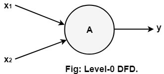
The Level-0 DFD, also called context diagram of the result management system is shown in fig. As the bubbles are decomposed into less and less abstract bubbles, the corresponding data flow may also be needed to be decomposed. 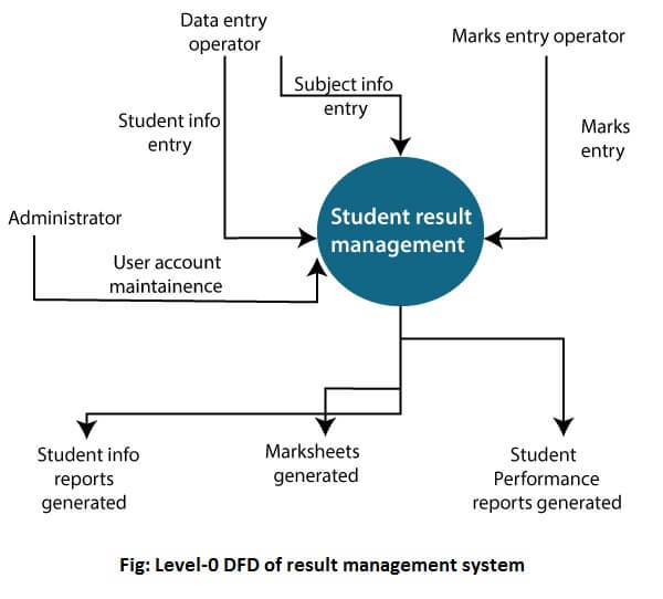
1-level DFD In 1-level DFD, a context diagram is decomposed into multiple bubbles/processes. In this level, we highlight the main objectives of the system and breakdown the high-level process of 0-level DFD into subprocesses. 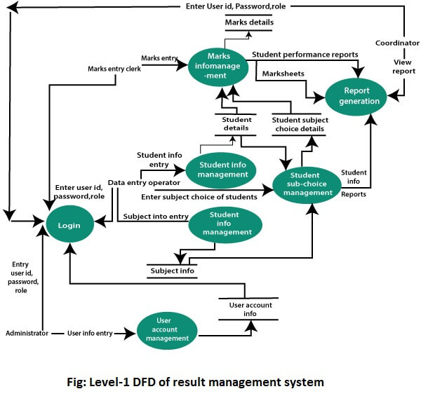
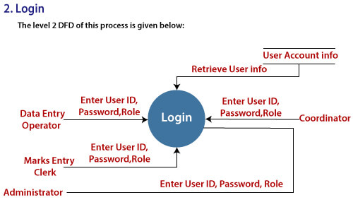
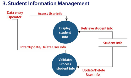
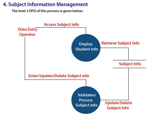
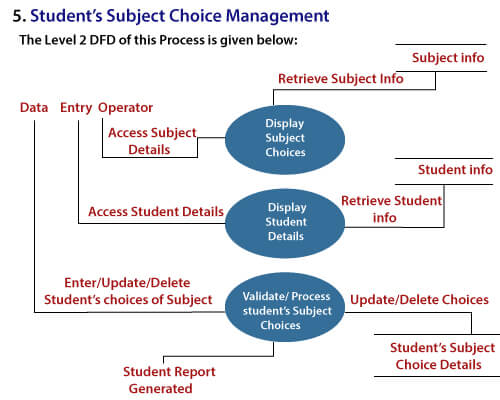
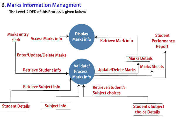
2-Level DFD 2-level DFD goes one process deeper into parts of 1-level DFD. It can be used to project or record the specific/necessary detail about the system's functioning. 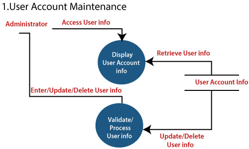
Next TopicData Dictionaries
|
 For Videos Join Our Youtube Channel: Join Now
Feedback
- Send your Feedback to [email protected]
Help Others, Please Share


