Spline command in SolidWorksSolidworks-spline-icon.png may be found under Tools > Sketch Entities > Spline. Spline Flyout > Spline in the Sketch Toolbar. 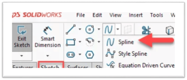
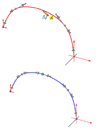
SOLIDWORKS splines' several types
Methods for Manipulating SplinesIn this illustration, I've drawn a rough drawing with a few building lines and then added proportions to adequately describe them. 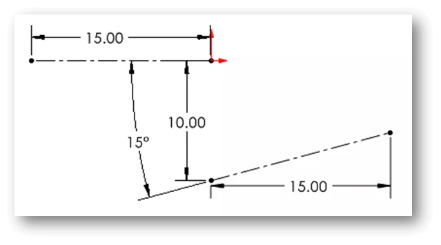
Establishing a SplineStart the Spline command, and then use the left mouse button to drop points into position to construct a spline. When additional points are added, the curve becomes more visible. I made a four-pointed spline for this illustration. Double-click the final point or use the Escape key on your keyboard to finish the spline. 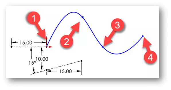
Displaying curve combsSometimes it helps to observe how the slope of curvature is represented visually. Simply right-click the spline and choose Display Curvature Combs to accomplish this. SOLIDWORKS's Display Curvature Combine Icon The curvature comb display may be adjusted by changing the scale and density. 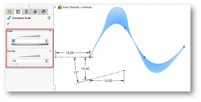
Control polygons displayedThe position of the spline points and the spline's curvature may both be modified using control polygons. Right-click the spline and select Show Control Polygons to enable Control Polygons. SOLIDWORKS Control Polygons Icon Display You may adjust the grips at each polygon vertex to change how the spline curves. 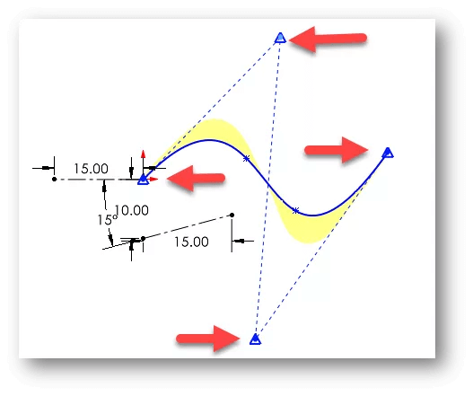
Dimensional AddingAdding dimensions between the spline points and other geometries is another technique to adjust the spline's curvature. 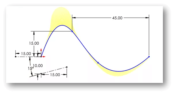
handle splineEach spline point's curvature can be controlled via spline handles. Click on the spline to reveal the handles. There are single-sided arrows at the beginning and finish points and grey, two-sided arrows on each through point. Making Spline Handles ActiveThere are three controls on spline handles. The grey colour of the spline handles indicates that they are inactive. Click and drag on one of the three control grips to turn on a spline handle. The tangency of the angle is managed by the diamond grip. 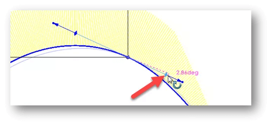
The tangency length is controlled by the arrow. 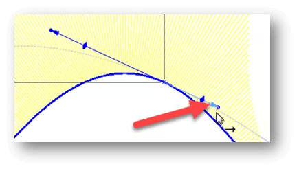
The arrow's location at the end determines both the tangency angle and the length in a single drag. 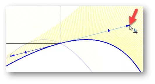
Increasing the Spline's PointsTo the spline, points may be added for more manipulation. To achieve this, choose Insert Spline Point with a right click on the spline. SOLIDWORKS: Add Spline Point Icon Next click the location where you want to add the extra point (s). Right-click on a spline point and select Delete to remove it. Remove Icon SOLIDWORKS Spline handles resetIt could be challenging to further manipulate spline handles to restore the original curvature after doing so. The spline handles can be moved back to their initial locations. Choose Reset All Handles in the Spline PropertyManager by clicking on any spline handle. Just the specified spline handle will be reset when this handle is reset. 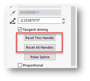
Giving Spline Handles DimensionFor more precise modifications, dimensions and relationships can be directly applied to the spline handle. Choose a spline handle arrow and click in the empty spot to add a dimension when Smart Dimension is enabled. The spline handle's length is controlled by this measurement. I'll put 60 inches on this measurement. Choose a spline handle arrow, then pick other geometry to create a dimension between them when Smart Dimension is active. I'll make a 115-degree angle between the handle and the horizontal construction line in this instance. 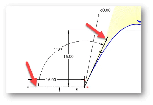
Indicate turning pointsWe may include a graphical indicator at each inflection (or change in curvature) along the spline. Right-click the spline and select Show Inflection Points to accomplish this. SOLIDWORKS: Display Inflection Points Icon Spline Style ToolThe ability to design a style spline is also available (or Bezier curve). Choose Style Spline from the Spline Flyout dropdown menu. Spline Style Tool Icon for SOLIDWORKS A smoother curve or a Bezier curve with a greater B-Spline degree are other options. We'll stick with Bezier for the sake of this example. Using Style Splines, we click polygon vertices into position rather than spline points. You must consider where the polygon vertices will be, which makes this distinct from inserting spline points. A very smooth outcome is displayed in the curvature comb display. Spline manipulation in fashionThe manipulation of style splines is quite similar to that of standard splines. Vertex actions on polygons include dragging, dimensioning, and adding relationships. In this illustration, I've inserted a dimension between two polygonal lines and an angled dimension between their vertices. By holding down the CTRL key while choosing the polygon lines, we may create relationships by picking the necessary one from the Context Toolbar. Additional Polygon Vertices to be AddedWe can add extra polygon control vertices to a Style spline just like we can add spline points to a B-Spline. Hover over one of the polygon construction lines, then select Insert Control Vertex from the context menu. In SOLIDWORKS, add a control vertex icon. The vertex may be moved by dragging it. Removing previously added connections may result from this. There are more parameters and controls available for splines than what we have covered here. But this ought to provide you a good place to start when making and applying splines. SplinesB-splines and style splines are the two forms of splines that the SOLIDWORKS programme supports. B-splines can be used to make intricate curves. Many controls, such as spline points, spline handles, and control polygons, can be used to design and change them. Several through points and spans can be present in a single B-spline (the region between through points). At each terminal, curvature limitations can be applied. You may balance the tangency vector and regulate the tangency direction at each through point. 
When a smooth curve is required, style splines based on Bézier curves are an excellent choice (that is, to assure curvature continuity). With control vertices, you may create and manage the curves. The curve's hull, or control polygon, is made up of the control vertices. A style spline only has one span between the ends since there are no through points. Style splines can be inferred for tangency or equal curvature. The points can be limited, and the sides of curves can be dimensioned. Moreover, these curves facilitate self-symmetry and reflection. 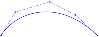
Points of SplineOne or more points can be added to splines using the Insert Spline Point command.
Spline points are insertedAdd spline points as follows:
Spline Points deletedSpline point deletion Choose a point and press the Delete key in an open drawing. Inserting Spline Points in a Video Understanding Solid works' SplinesA spline is a continuous curve that travels through user-specified discrete points. It is a curve that, unlike lines and arcs, is characterized by its continually changing curvature to produce an organic shape. Splines may often be produced in Solid works by utilizing two or even more endpoints. A complexly shaped profile is made using splines. To create the curve, points are inserted. Splines are frequently underdefined in drawings, unlike traditional geometry. Constricting the curvature while preserving a supple, fluid form can be challenging. Spline types supported by SolidWorks:B-splines and style splines are the two forms of splines that are supported by the SOLIDWORKS programme. B-SPLINESB-splines, sometimes referred to as base-splines, are used to design intricate curves. Many controls, such as spline points, spline handles, and control polygons, can be used to design and change them. Several through points and spans can be present in a single B-spline (the region between through points). At each terminal, curvature limitations can be applied. You may balance the tangency vector and adjust the tangency direction at each position. Procedures For Making a Multipoint B-SplineMultiple point splines can be made by:
One or more points can be added to splines using the Insert Spline Point command. Spline points allow you to:
Add spline points as follows:
One of the handles will turn from grey to blue once you move it, showing that it was moved and activated. The grey handles vanish when the spline is deselected, but the blue ones are still discernible. What Do Spline Control Polygons Do?A 2D or 3D spline's shape can be modified by dragging or changing the values of the control polygon nodes. The X and Y coordinates (in 2D splines) and X, Y, and Z coordinates (in 3D splines) in the Property Manager are updated when the control points' (nodes') positions are changed. Spline Polygon Property Manager may be accessed here:
Spline Style When a smooth curve is required, style splines based on Bezier curves are an excellent choice (that is, to assure curvature continuity). With control vertices, you may create and manage the curves. A control polygon or the curve's hull is created by the control vertices. A style spline only has one span between the ends since there are no through points. Style splines can be inferred from tangency or equal curvature. The points can be limited, and the sides of curves can be dimensioned. Moreover, these curves facilitate self-symmetry and reflection. What Do Spline Control Vertices Do?Fit points or control vertices are used to define splines. Fit points naturally line up with the spline, whereas control vertices establish a control frame. Control frames offer a practical way to curve the spline. Each approach has benefits. How Can I Locally Modify a Control Vertex or Vertices in the Graphics View Area? You may drag and modify a style spline's form using local edit without impacting nearby style splines. When dealing with several linked but loosely limited type splines, this option is useful. Using Local edit, change a style spline as follows:
Understanding Solidwork's SplinesA spline is a continuous curve that travels through user-specified discrete points. It is a curve that, unlike lines and arcs, is characterized by its continually changing curvature to produce an organic shape. Splines may often be produced in Solidworks by utilizing two or even more endpoints. A complexly shaped profile is made using splines. To create the curve, points are inserted. Splines are frequently underdefined in drawings, unlike traditional geometry. Constricting the curvature while preserving a supple, fluid form can be challenging.
Next TopicFreeze command in SolidWorks
|
 For Videos Join Our Youtube Channel: Join Now
Feedback
- Send your Feedback to [email protected]
Help Others, Please Share


 Spline Icon for SOLIDWORKS With the use of controls like spline points, spline handles, and control polygons, the Spline command constructs a B-spline that may be altered.
 Using SOLIDWORKS' Style Spline Icon Based on Bezier curves, the Style Spline command was created. They are specified by a control polygon's control vertices.