| |

SSBC (Single Sideband with Carrier)SSB modulation transmits the information using a single sideband rather than two sidebands. It not only saves the spectrum space but also saves the bandwidth. The bandwidth of SSB gets reduced to half compared to DSB (Double Sideband) modulation. SSBC is different from SSBSC. Here, the carrier is transmitted along with the baseband signal. The carrier signal is further added by multiplying it with the baseband signal at the recovery end. In SSBSC, the carrier was not transmitted along with the signal to improve efficiency. SSBSC is the only signal that has an efficiency of 100%. SSB generation from DSBLet's discuss the difference between the DSB (Double Sideband Modulation) and SSB (Single Sideband Modulation) with the help of a diagram. We will also discuss how SSB can be generated from DSB. The generation of double sidebands by multiplying the carrier signal with the baseband signal is shown below: 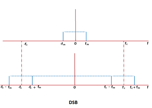
The first signal is the original message signal, and the below signal is the two sidebands on both sides of the carrier frequency. Two-thirds of the power in DSBC is wasted. The power is distributed among the two sidebands, which is inefficient. The efficiency of DSBC is 33.33%.It is also known as DSB-FC (Double Sideband Full Carrier) transmission. If the carrier is suppressed, the efficiency can be increased. Such a method is known as DSBSC (Double Sideband Suppress Carrier). Now, there is no carrier, and the power is distributed only among the sidebands, which is equal. It means that we can easily use filters to separate the two sidebands. The efficiency of DSBSC is 50%. It is known as SSB (Single Sideband Modulation). If the carrier is further suppressed to improve the efficiency, it is known as SSBSC (Single Sideband Suppressed Carrier). The efficiency of SSBSC is 100%. The filter in SSB selects either band from the DSBSC signal. Suppose it selects the upperband. It is shown below: 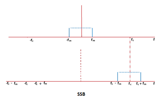
The modulation and demodulation of the Single Sideband is known SSB modulation and SSB demodulation. We have already discussed the modulation and demodulation process of SSBSC. Here, we will discuss the SSBC modulation and demodulation. SSBC ModulatorThe modulation process of SSBC is similar to that of SSBSC (Single Sideband Suppress Carrier). Let's discuss a short summary of the SSBC modulation process. The block diagram of the SSBC modulator is shown below: 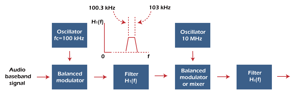
It consists of two oscillators, two balance modulators, and two filters. The baseband signals with the carrier are first applied to the balance modulator. The output of the modulator will be the upper sideband and the lower sideband. The function of the filter is to select only one sideband based on the frequency of the first oscillator. The frequency selection of the oscillator is necessary, because it helps in the separation of the two sidebands. The separation frequency is given by: Separation frequency = 2 (lowest frequency spectral component of the baseband signal) The uses of two oscillators are essential to balance the frequency change at the output. The carrier, along with the signal, does not appear at the output of the first balance modulator. It is better to suppress the carrier at the output of the modulator and add it to the signal at a later point in a specific manner. It becomes difficult for the balanced modulator to balance both the carrier and the baseband signal. It also leads to a time delay in the transmission process. The function of the second balanced modulator is to add the carrier single that was suppressed before. The second filter at the end helps in recovering the baseband signal. We can also use the phase shift method to generate the SSBC signal. It is discussed in detail in SSBSC. SSBC DemodulatorEnvelope detector is the method used for demodulation of the SSBC signal. Let the message signal be Amcosωmt and the carrier signal be AcosωCt. Where, Am is the amplitude constant of the message signal The modulation of the two can be represented as: F1(t) = A[1 + Amcosωmt] cosωCt F1(t) = AcosωCt + AAmcosωCt cosωmt F1(t) = AcosωCt + AAm/2 [cos(ωC + ωm)t + cos(ωC - ωm)t] If we remove one of the sideband, the modulated signal can be represented as: F2(t) = AcosωCt + AAm/2 cos(ωC + ωm)t The circuit of the envelope detector is shown below: 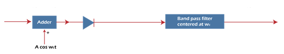
It comprises of the adder, diode, and the bandpass filter. We need to form the envelope of the signal f2(t) to find the response of the diode demodulator. F2(t) = AcosωCt + AAm/2 cosωCtcosωmt - AAm/2 sinωCtsinωmt Here, we have expanded the term cos(ωC + ωm)t using the trigonometric formula of cos (a + b). F2(t) = A(1 + Am/2 cosωmt) - AAm/2 sinωCtsinωmt The amplitude of A for values very less than the amplitude constant of the message signal (Am << 1) will be: F2(t) = A(1 + Am/2 cosωmt) We can observe that the output of the baseband signal is half as large if one sideband is suppressed as compared to both the sidebands. The recovery of baseband signal in SSBC is similar to that of DSBC. Most of the AM receivers are provided with the adjustable local oscillator. It helps to adjust the frequency according to the requirements. It serves as a local carrier and is added with the SSB signal. But, such Am demodulators produce some distortion. We can also compare the envelope detector method with the synchronous demodulation. The synchronous distortion is very small, but the receiver should be aware of both the frequency and phase distortion. In the case of the diode demodulator, the distortion is produced due to the diode demodulator. The receiver has the information on only frequency distortion. The chances of phase distortion are very less.
Next TopicVSBSC
|
 For Videos Join Our Youtube Channel: Join Now
Feedback
- Send your Feedback to [email protected]
Help Others, Please Share


