| |

UML Class DiagramThe class diagram depicts a static view of an application. It represents the types of objects residing in the system and the relationships between them. A class consists of its objects, and also it may inherit from other classes. A class diagram is used to visualize, describe, document various different aspects of the system, and also construct executable software code. It shows the attributes, classes, functions, and relationships to give an overview of the software system. It constitutes class names, attributes, and functions in a separate compartment that helps in software development. Since it is a collection of classes, interfaces, associations, collaborations, and constraints, it is termed as a structural diagram. Purpose of Class DiagramsThe main purpose of class diagrams is to build a static view of an application. It is the only diagram that is widely used for construction, and it can be mapped with object-oriented languages. It is one of the most popular UML diagrams. Following are the purpose of class diagrams given below:
Benefits of Class Diagrams
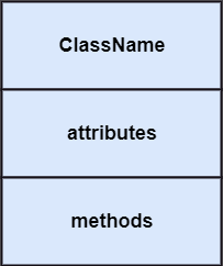
Vital components of a Class DiagramThe class diagram is made up of three sections:
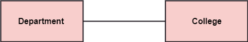
RelationshipsIn UML, relationships are of three types:
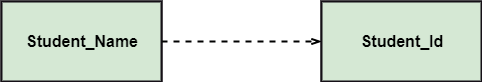
Multiplicity: It defines a specific range of allowable instances of attributes. In case if a range is not specified, one is considered as a default multiplicity. For example, multiple patients are admitted to one hospital. 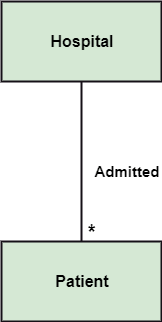
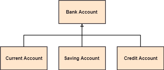
Aggregation: An aggregation is a subset of association, which represents has a relationship. It is more specific then association. It defines a part-whole or part-of relationship. In this kind of relationship, the child class can exist independently of its parent class. The company encompasses a number of employees, and even if one employee resigns, the company still exists. 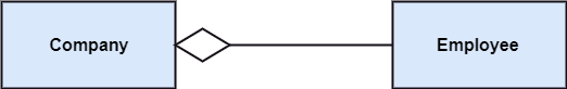
Composition: The composition is a subset of aggregation. It portrays the dependency between the parent and its child, which means if one part is deleted, then the other part also gets discarded. It represents a whole-part relationship. A contact book consists of multiple contacts, and if you delete the contact book, all the contacts will be lost. 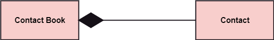
Abstract ClassesIn the abstract class, no objects can be a direct entity of the abstract class. The abstract class can neither be declared nor be instantiated. It is used to find the functionalities across the classes. The notation of the abstract class is similar to that of class; the only difference is that the name of the class is written in italics. Since it does not involve any implementation for a given function, it is best to use the abstract class with multiple objects. Let us assume that we have an abstract class named displacement with a method declared inside it, and that method will be called as a drive (). Now, this abstract class method can be implemented by any object, for example, car, bike, scooter, cycle, etc. 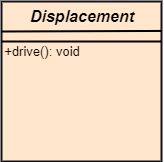
How to draw a Class Diagram?The class diagram is used most widely to construct software applications. It not only represents a static view of the system but also all the major aspects of an application. A collection of class diagrams as a whole represents a system. Some key points that are needed to keep in mind while drawing a class diagram are given below:
Class Diagram ExampleA class diagram describing the sales order system is given below. 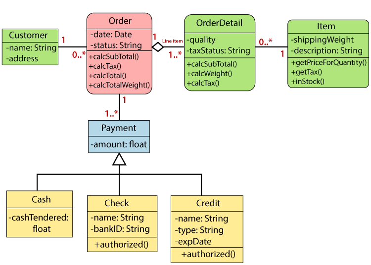
Usage of Class diagramsThe class diagram is used to represent a static view of the system. It plays an essential role in the establishment of the component and deployment diagrams. It helps to construct an executable code to perform forward and backward engineering for any system, or we can say it is mainly used for construction. It represents the mapping with object-oriented languages that are C++, Java, etc. Class diagrams can be used for the following purposes:
Next TopicUML Object Diagram
|
 For Videos Join Our Youtube Channel: Join Now
Feedback
- Send your Feedback to [email protected]
Help Others, Please Share


