| |

UML Component DiagramA component diagram is used to break down a large object-oriented system into the smaller components, so as to make them more manageable. It models the physical view of a system such as executables, files, libraries, etc. that resides within the node. It visualizes the relationships as well as the organization between the components present in the system. It helps in forming an executable system. A component is a single unit of the system, which is replaceable and executable. The implementation details of a component are hidden, and it necessitates an interface to execute a function. It is like a black box whose behavior is explained by the provided and required interfaces. Notation of a Component Diagrama) A component 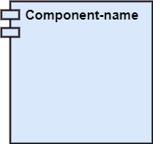
b) A node 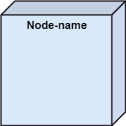
Purpose of a Component DiagramSince it is a special kind of a UML diagram, it holds distinct purposes. It describes all the individual components that are used to make the functionalities, but not the functionalities of the system. It visualizes the physical components inside the system. The components can be a library, packages, files, etc. The component diagram also describes the static view of a system, which includes the organization of components at a particular instant. The collection of component diagrams represents a whole system. The main purpose of the component diagram are enlisted below:
Why use Component Diagram?The component diagrams have remarkable importance. It is used to depict the functionality and behavior of all the components present in the system, unlike other diagrams that are used to represent the architecture of the system, working of a system, or simply the system itself. In UML, the component diagram portrays the behavior and organization of components at any instant of time. The system cannot be visualized by any individual component, but it can be by the collection of components. Following are some reasons for the requirement of the component diagram:
When to use a Component Diagram?It represents various physical components of a system at runtime. It is helpful in visualizing the structure and the organization of a system. It describes how individual components can together form a single system. Following are some reasons, which tells when to use component diagram:
How to Draw a Component Diagram?The component diagram is helpful in representing the physical aspects of a system, which are files, executables, libraries, etc. The main purpose of a component diagram is different from that of other diagrams. It is utilized in the implementation phase of any application. Once the system is designed employing different UML diagrams, and the artifacts are prepared, the component diagram is used to get an idea of implementation. It plays an essential role in implementing applications efficiently. Following are some artifacts that are needed to be identified before drawing a component diagram:
Following are some points that are needed to be kept in mind after the artifacts are identified:
Example of a Component DiagramA component diagram for an online shopping system is given below: 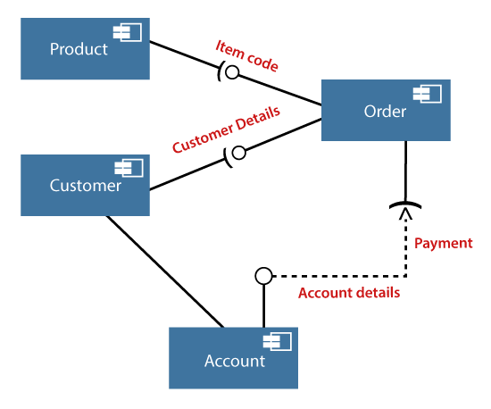
Where to use Component Diagrams?The component diagram is a special purpose diagram, which is used to visualize the static implementation view of a system. It represents the physical components of a system, or we can say it portrays the organization of the components inside a system. The components, such as libraries, files, executables, etc. are first needed to be organized before the implementation. The component diagram can be used for the followings:
Next TopicUML Deployment Diagram
|
 For Videos Join Our Youtube Channel: Join Now
Feedback
- Send your Feedback to [email protected]
Help Others, Please Share


