| |

UML Deployment DiagramThe deployment diagram visualizes the physical hardware on which the software will be deployed. It portrays the static deployment view of a system. It involves the nodes and their relationships. It ascertains how software is deployed on the hardware. It maps the software architecture created in design to the physical system architecture, where the software will be executed as a node. Since it involves many nodes, the relationship is shown by utilizing communication paths. Purpose of Deployment DiagramThe main purpose of the deployment diagram is to represent how software is installed on the hardware component. It depicts in what manner a software interacts with hardware to perform its execution. Both the deployment diagram and the component diagram are closely interrelated to each other as they focus on software and hardware components. The component diagram represents the components of a system, whereas the deployment diagram describes how they are actually deployed on the hardware. The deployment diagram does not focus on the logical components of the system, but it put its attention on the hardware topology. Following are the purposes of deployment diagram enlisted below:
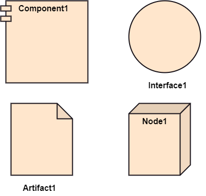
Symbol and notation of Deployment diagramThe deployment diagram consist of the following notations:
How to draw a Deployment Diagram?The deployment diagram portrays the deployment view of the system. It helps in visualizing the topological view of a system. It incorporates nodes, which are physical hardware. The nodes are used to execute the artifacts. The instances of artifacts can be deployed on the instances of nodes. Since it plays a critical role during the administrative process, it involves the following parameters:
One of the essential elements of the deployment diagram is the nodes and artifacts. So it is necessary to identify all of the nodes and the relationship between them. It becomes easier to develop a deployment diagram if all of the nodes, artifacts, and their relationship is already known. Example of a Deployment diagramA deployment diagram for the Apple iTunes application is given below. The iTunes setup can be downloaded from the iTunes website, and also it can be installed on the home computer. Once the installation and the registration are done, iTunes application can easily interconnect with the Apple iTunes store. Users can purchase and download music, video, TV serials, etc. and cache it in the media library. Devices like Apple iPod Touch and Apple iPhone can update its own media library from the computer with iTunes with the help of USB or simply by downloading media directly from the Apple iTunes store using wireless protocols, for example; Wi-Fi, 3G, or EDGE. 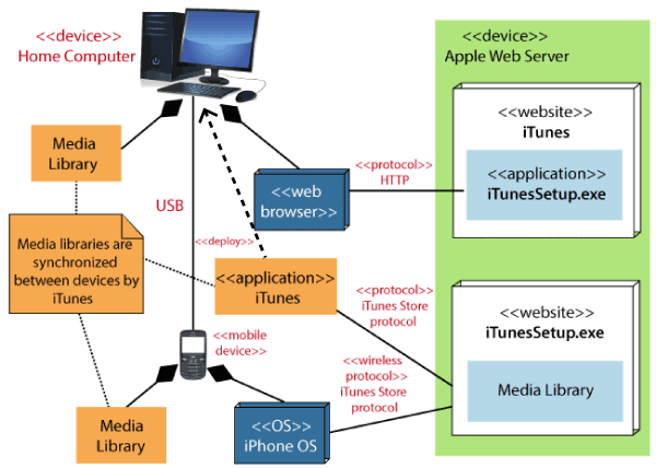
When to use a Deployment Diagram?The deployment diagram is mostly employed by network engineers, system administrators, etc. with the purpose of representing the deployment of software on the hardware system. It envisions the interaction of the software with the hardware to accomplish the execution. The selected hardware must be of good quality so that the software can work more efficiently at a faster rate by producing accurate results in no time. The software applications are quite complex these days, as they are standalone, distributed, web-based, etc. So, it is very necessary to design efficient software. Deployment diagrams can be used for the followings:
Next TopicUML Interaction Diagram
|
 For Videos Join Our Youtube Channel: Join Now
Feedback
- Send your Feedback to [email protected]
Help Others, Please Share


