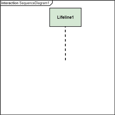
UML Interaction DiagramAs the name suggests, the interaction diagram portrays the interactions between distinct entities present in the model. It amalgamates both the activity and sequence diagrams. The communication is nothing but units of the behavior of a classifier that provides context for interactions. A set of messages that are interchanged between the entities to achieve certain specified tasks in the system is termed as interaction. It may incorporate any feature of the classifier of which it has access. In the interaction diagram, the critical component is the messages and the lifeline. In UML, the interaction overview diagram initiates the interaction between the objects utilizing message passing. While drawing an interaction diagram, the entire focus is to represent the relationship among different objects which are available within the system boundary and the message exchanged by them to communicate with each other. The message exchanged among objects is either to pass some information or to request some information. And based on the information, the interaction diagram is categorized into the sequence diagram, collaboration diagram, and timing diagram. The sequence diagram envisions the order of the flow of messages inside the system by depicting the communication between two lifelines, just like a time-ordered sequence of events. The collaboration diagram, which is also known as the communication diagram, represents how lifelines connect within the system, whereas the timing diagram focuses on that instant when a message is passed from one element to the other. Notation of an Interaction Diagram
Purpose of an Interaction DiagramThe interaction diagram helps to envision the interactive (dynamic) behavior of any system. It portrays how objects residing in the system communicates and connects to each other. It also provides us with a context of communication between the lifelines inside the system. Following are the purpose of an interaction diagram given below:
How to draw an Interaction Diagram?Since the main purpose of an interaction diagram is to visualize the dynamic behavior of the system, it is important to understand what a dynamic aspect really is and how we can visualize it. The dynamic aspect is nothing but a screenshot of the system at the run time. Before drawing an interaction diagram, the first step is to discover the scenario for which the diagram will be made. Next, we will identify various lifelines that will be invoked in the communication, and then we will classify each lifeline. After that, the connections are investigated and how the lifelines are interrelated to each other. Following are some things that are needed:
Use of an Interaction DiagramThe interaction diagram can be used for:
Next TopicUML Use Case Diagram
|
 For Videos Join Our Youtube Channel: Join Now
Feedback
- Send your Feedback to [email protected]
Help Others, Please Share


