| |

Verilog D LatchA flip-flop captures data at its input at the negative or positive edge of a clock. The important thing is that whatever happens to data after the clock edge until the next clock edge will not be reflected in the output. A latch does not capture at the edge of a clock; instead, the output follows input as long as it is asserted. The D latch is used to store one bit of data. The D latch is essentially a modification of the gated SR latch. The following image shows the parameters of the D latch in Verilog. The input D is the data to be stored. The input G is used to control the storing. The outputs Q and Qn are the stored data and the complement of the stored data, respectively. 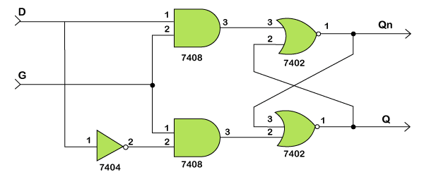
ExampleIn this example, we have a latch with three inputs and one output. The input d stands for data, which can be either 0 or 1, rstn stands for active-low reset, and en stands for enabling, which is used to make the input data latch to the output. 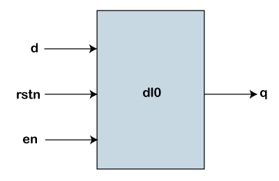
Reset being active-low means that the design element will be reset when this input goes to 0 or reset is active when its value is low. The value of output q is dictated by the inputs d, en and rstn. NOTE: The sensitivity list to the always block contains all the signals required to update the output.This block will be triggered whenever any of the signals in the sensitivity list changes its value. Also, q will get the value of d only when en is high and hence is a positive latch. Hardware Schematic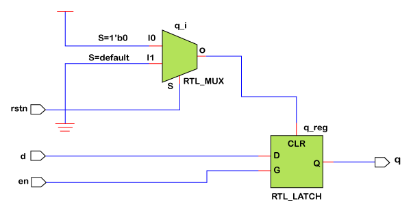
TestbenchTo make our testbench assert and deassert signals in a more random manner, we have declared a reg variable called delay of size 3 bits so that it can take any value from 0 to 7. Then the delay variable is used to delay the assignment of d and en to get different patterns in every loop. The above code produce the following output, such as: ncsim> run [0] en=0 d=0 q=0 [11] en=1 d=0 q=0 [18] en=0 d=0 q=0 [19] en=0 d=1 q=0 [20] en=1 d=1 q=1 [25] en=1 d=0 q=0 [27] en=0 d=0 q=0 [32] en=0 d=1 q=0 [33] en=1 d=1 q=1 [34] en=1 d=0 q=0 ncsim: *W,RNQUIE: Simulation is complete.
Next TopicVerilog Ripple Counter
|
 For Videos Join Our Youtube Channel: Join Now
Feedback
- Send your Feedback to [email protected]
Help Others, Please Share


