| |

Gate Level ModelingIn Verilog, most of the digital designs are done at a higher level of abstraction like RTL. However, it becomes natural to build smaller deterministic circuits at a lower level by using combinational elements such as AND and OR. Modeling done at this level is called gate-level modeling as it involves gates and has a one to one relationship between a hardware schematic and the Verilog code. Verilog supports a few basic logic gates known as primitives, as they can be instantiated, such as modules, and they are already predefined. Gate level modeling is virtually the lowest level of abstraction because the switch-level abstraction is rarely used. Gate level modeling is used to implement the lowest-level modules in a design, such as multiplexers, full-adder, etc. Verilog has gate primitives for all basic gates. Verilog supports built-in primitive gates modeling. The gates supported are multiple-input, multiple-output, tri-state, and pull gates. The multiple-input gates are and, nand, or, nor, xor, and xnor whose number of inputs are two or more, and has only one output. The multiple-output gates are buf and not whose output is one or more and has only one input. The language also supports the modeling of tri-state gates, including bufif0, bufif1, notif0, and notif1. These gates have one input, one control signal, and one output. The pull gates are pullup and pulldown with a single output only. Syntax Following is the basic syntax for each type of gates with zero delays, such as: One can also have multiple instances of the same type of gate in one construct separated by a comma: The gate-level modeling is useful when a circuit is a simple combinational, such as a multiplexer. A multiplexer is a simple circuit that connects one of many inputs to an output. Gate PrimitivesGate primitives are predefined modules in Verilog, which are ready to use. There are two classes of gate primitives:
1. Single input gate primitivesSingle input gate primitives have a single input and one or more outputs. The gate primitive are not, buf, notif, and bufif also have a control signal. The gates propagate only if the control signal is asserted, else the output is high impedance state. 1.1 Not, buf Gates These gates have only one scalar input but may have multiple outputs. buf stands for a buffer and transfer the value from input to the output without any change in polarity. not stands for an inverter which inverts the polarity of the signal at its input. So a 0 at its input will yield a 1 and vice versa. Syntax Example 1.2 Bufif, Notif Gates Bufif and notif primitives are buffers and inverters, respectively, with an additional control signal to enable the output is available through bufif and notif primitives. These gates have a valid output only if the control signal is enabled else, and the output will be in high impedance. There are two versions of these, one with the normal polarity of control indicated by a 1 such as bufif1 and notif1. And second with the inverted polarity of control indicated by a 0 such as bufif0 and notif0. Syntax Example 2. Multiple Input Gate PrimitivesMultiple input gate primitives include AND, OR, XOR, NAND, NOR, and XNOR. They may have multiple inputs and a single output. 2.1 AND, OR, XOR Gates An AND, OR, and an XOR gate need multiple scalar inputs and produce a single scalar output. The first terminal in the argument list to these primitives is the output, which changed as any inputs shift. Syntax Example 1.2 NAND, NOR, XNOR Gates The inverse of all the above gates is NAND, NOR, and XNOR. The same design from above is reused only that the primitives are interchanged with their inverse versions. Syntax Example All these gates may also have more than two inputs. Gate Level Modeling of a MultiplexerThe gate-level circuit diagram of 4x1 mux is shown below. It is used to write a module for 4x1 mux. 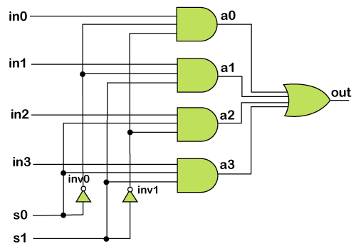
Gate Level Modeling of Full-adderHere is the implementation of a full adder using the half adder. 1. Half adder 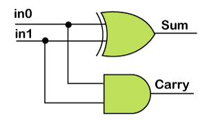
2. Full adder 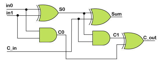
Next TopicSwitch Level Modeling
|
 For Videos Join Our Youtube Channel: Join Now
Feedback
- Send your Feedback to [email protected]
Help Others, Please Share


