| |

JK Flip FlopThe JK flip-flop is the most versatile of the basic flip flops. A JK flip-flop is used in clocked sequential logic circuits to store one bit of data. It is almost identical in function to an SR flip flop. The only difference is eliminating the undefined state where both S and R are 1. Due to this additional clocked input, a JK flip-flop has four possible input combinations, such as "logic 1", "logic 0", "no change" and "toggle". Hardware Schematic 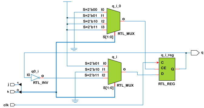
Example We will program JK Flip Flop in Verilog and write a testbench for the same code. Testbench Edge-triggered JK Flip-flopThe type of JK flip-flop described here is an edge-triggered JK flip-flop. It is built from two gated latches: one a master gated D latch and a slave gated SR latch. This is a modified version of the edge-triggered D flip flop. The flip-flop's outputs are fed back and combined with the inputs. The master takes the flip-flop's inputs, such as J (set), K (reset), and C (clock). The clock input is inverted and fed into the D latch's gate input. The slave takes the master's outputs as inputs (Q to S and Qn to R) and complements the master's clock input. The slave's outputs are the flip-flop's outputs. This difference in clock inputs between the two latches disconnects them and eliminates the transparency between the flip-flop's inputs and outputs. The below schematic image shows a positive edge-triggered JK flip-flop. The two inputs J and K, are used to set and reset the data, respectively. They can also be used to toggle the data. The clock input C is used to control both the master and slave latches, making sure only one of the latches can set its data at any given time. When C has the value 0, the master latch can set its data, and the slave latch cannot. When C has the value 1, the slave can set its data, and the master cannot. When C transitions from 0 to 1, the master has its outputs set, which reflect the flip-flop's inputs when the transition occurred. The outputs Q and Qn are the flip-flop's stored data and the complement of the flip-flop's stored data. 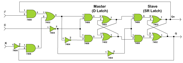
The schematic symbol for a 7476 edge-triggered JK flip-flop is shown below. This chip has inputs to set and reset the flip-flop's data asynchronously. 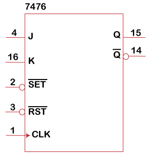
Example Below is the Verilog code for a positive edge-triggered JK flip-flop. An active-low reset input has been added to asynchronously clear the flip-flop.
Next TopicD Flip-Flop
|
 For Videos Join Our Youtube Channel: Join Now
Feedback
- Send your Feedback to [email protected]
Help Others, Please Share


