| |

Verilog Mod-N CounterCounters are sequential logic devices that follow a predetermined sequence of counting states triggered by an external clock (CLK) signal. The number of states or counting sequences through which a particular counter advances before returning to its original first state is called the modulus (MOD). In other words, the modulus (or modulo) is the number of states the counter counts and is the dividing number of the counter. Modulus Counters, or MOD counters, are defined based on the number of states that the counter will sequence before returning to its original value. For example, a 2-bit counter that counts from 002 to 112 in binary, 0 to 3 in decimal, has a modulus value of 4 ( 00 → 1 → 10 → 11, and return to 00 ); therefore, be called a modulo-4, or mod-4, counter. Note also that it has taken four clock pulses to get from 00 to 11. In this example, there are only two bits ( n = 2 ) then the maximum number of possible output states (maximum modulus) for the counter is 2n = 22 or 4. However, counters can be designed to count to any 2n states in their sequence by cascading together multiple counting stages to produce a single modulus or MOD-N counter. Therefore, a "Mod-N" counter will require the "N" number of flip-flops connected to count a single data bit while providing 2n different output states (n is the number of bits). Note that N is always a whole integer value. Then we can see that MOD counters have a modulus value that is an integral power of 2, that is, 2, 4, 8, 16 and so on to produce an n-bit counter depending on the number of flip-flops used, and how they are connected, determining the type and modulus of the counter. ExampleTestbench Following is the testbench for the same example given above, such as: The output looks like: ncsim> run T=0 rstn=0 out=0xx T=10 rstn=0 out=0x0 T=30 rstn=1 out=0x0 T=50 rstn=1 out=0x1 T=70 rstn=1 out=0x2 T=90 rstn=1 out=0x3 T=110 rstn=1 out=0x4 T=130 rstn=1 out=0x5 T=150 rstn=1 out=0x6 T=170 rstn=1 out=0x7 T=190 rstn=1 out=0x8 T=210 rstn=1 out=0x9 T=230 rstn=1 out=0xa T=250 rstn=1 out=0x0 T=270 rstn=1 out=0x1 T=290 rstn=1 out=0x2 T=310 rstn=1 out=0x3 T=330 rstn=1 out=0x4 T=350 rstn=1 out=0x5 T=370 rstn=1 out=0x6 T=390 rstn=1 out=0x7 T=410 rstn=1 out=0x8 Simulation complete via $finish(1) at time 430 NS + 0 Mod 6 Up CounterThis is a counter that resets at a chosen number. For example, a two-digit decimal counter, left to its own devices, will count from 00 to 99. This is not much use for a clock unless you have 100 seconds minutes. 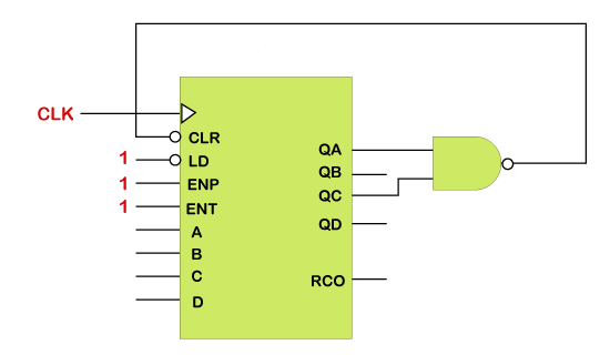
To fix the problem, the counter must go from 00 to 59. This is achieved by detecting a 6 in the left-hand digit and using it to reset the counter to zero. This would be a Modulo 6 Counter or 60 if we included both digits. 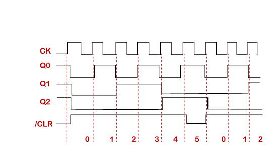
Mod 5 Down CounterSuppose we want to design a MOD-5 counter. First, we know that "m = 5", so 2n must be greater than 5. 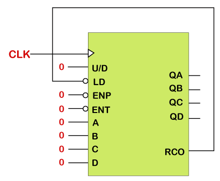
As 21 = 2, 22 = 4, 23 = 8, and 8 is greater than 5, then we need a counter with three flip-flops (N = 3) giving us a natural count of 000 to 111 in binary (0 to 7 decimal). 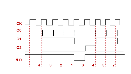
Next TopicVerilog Johnson Counter
|
 For Videos Join Our Youtube Channel: Join Now
Feedback
- Send your Feedback to [email protected]
Help Others, Please Share


