| |

Wien bridge oscillatorWien bridge oscillator is a type of phase shift oscillator which generates sinusoidal waves at the output. The Wien bridge oscillator was named after Max Karl Wien was based on the bridge circuit developed in the 1890s. It is one of the simplest oscillators known for its audio applications. ConstructionThe Wien bridge oscillator includes two capacitors (charge storing element) and four resistors. The other component of the circuit is an inverting amplifier like operational amplifiers or transistors. Here, the circuit uses two transistors. The two combinations in the circuit are one series combination, and one parallel combination of RC. The circuit of the Wien bridge oscillator is shown below: 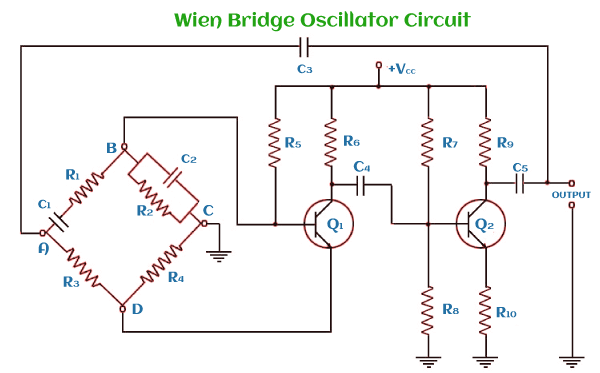
It has two paths for feedback, positive feedback and negative feedback. Frequency of OscillationsThe frequency of oscillations is given by: 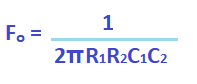
The frequency of oscillations when both the resistors and capacitors have equal value is given by: R1 = R2 = R C1 = C2 = C 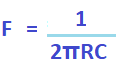
A bandpass filter is formed by resistors and capacitors R1, R2, C1, and C2. DerivationThe derivation will provide us with the condition for sustained oscillations. It is one of the methods to overcome the drawback of the Wien bridge oscillator. The equivalent circuit diagram of the Wien bridge oscillator can be represented as: 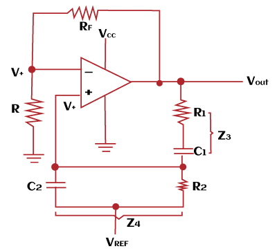
Z1 = R Z2 = RF Z3 = (R1 + 1/sC1) Z4 = (R2 || 1/sC2) Where, Z is the impedance RF is the feedback resistance (R1 + 1/sC1) is the series combination of R1 and C1. (R2 || 1/sC2) or [(R2/(1 + R2sC2)) is the parallel combination of R2 and C2 The positive feedback voltage (V+) is connected at the non-inverting terminal of the amplifier. It is given by: V+ = VO [Z4 (Z3 + Z4)] V+ = VO [(R2/1 + R1sC2) / ((R2/1 + R2sC2 + R1 + 1/sC1))] B = V+ / VO = 1/ (1 + R1sC2 + R1/ R2 + 1/ R2sC1 + C2/ C1) Put, s = jωo (ωo is the oscillation frequency) Equating the values of ω1 = 1/ R1C2 and ω2 = 1/ R2C1, we get: B = V+ / VO = 1/ (1 + R1/ R2 + C2/ C1 + j (ωo/ ω1 - ω2/ ωo)) The capacitor and the resistor can produce the phase shift of total 180 degrees provided by the oscillating frequencies. As discussed, a single RC network provides a maximum phase shift of 90 degrees. Two RC networks can thus contribute a maximum of 180 degrees phase shift. To find the overall feedback, let's assume, R1 = R2 = R C1 = C2 = C, and ω1 = ω2 = ωo The feedback is given by: B = 1/ (1 + R/ R + C/ C + j (ωo/ ωo - ωo / ωo)) B = 1/ (1 + R/ R + C/ C +0) B = 1/ (1 + 1 + 1) B = 1/ 3 If AB = 1 B = 1/3 The gain will be (A) = 3 The feedback from the circuit can be represented as: B = 1 + RF/R 3 = 1 + RF/R RF/R = 2 RF = 2R It is the condition for the sustained oscillations of the Wien bridge oscillator. It states that the product of the magnitude and feedback is one. The total feedback of the oscillator is calculated to ensure positive feedback, i.e., the phase shift of 0 or 360 degrees. It further maintains the periodic oscillations of the system. The sustained oscillations are based on the Barkhausen criteria. Phase shiftIn the case of RC phase shift oscillators, the total phase shift for positive feedback (0 or 360 degrees) was utilized from the phase network at the feedback path and the amplifier. But, in the case of Wien bridge oscillator, the two transistors provide a phase shift of 180 degrees each. Thus, the total phase shift to ensure positive feedback is: Phase shift = 180 (transistor) + 180 (transistor) Phase shift = 360 degrees Phase shift = 360 degrees = 0 degrees The output and the phase shift graph of the Wien bridge oscillator are shown below: 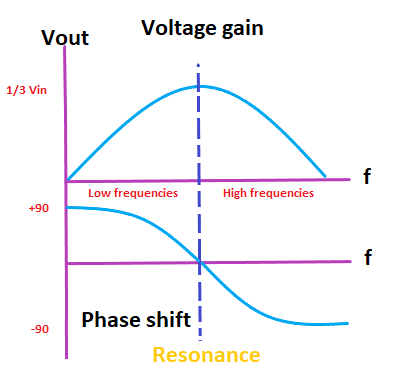
The above graph depicts that the phase shift is positive at low frequencies, while at high frequencies, it is negative. The negative phase shift produces phase delays. At the middle of the graph, the resonant frequency is determined, which is given by:
As discussed in the above derivation, the output voltage equals to 1/3rd of the input voltage to allow oscillations to occur. History
AdvantagesThe advantages of the Wien bridge oscillator are as follows:
DisadvantagesThe disadvantages of the Wien bridge oscillator are as follows:
Numerical ExamplesLet's discuss two examples based on the Wien bridge oscillators. Example: 1 In the Wien Bridge oscillator, R1 = 10k Ohms, R2 = 5k Ohms, XC1 = 10k Ohms, and XC2 = 5k Ohms. Find the two impedances of the circuit. Solution: Given: R1 = 10k Ohms = 104 Ohms R2 = 5k Ohms = 5 x 10³ Ohms XC1 = 10k Ohms = 104 Ohms XC2 = 5k Ohms = 5 x 10³ Ohms X is the reactance and is defined as the combined effect of resistance and resonance opposed by the current. There are two impedances in the Wien bridge oscillator, series and parallel. Let the two impedances be Z1 and Z2. Z1 = R1 + XC1 = 20k Ohms 1/Z2 = 1/R2 + 1/ XC2 1/Z2 = 1/5000 + 1/5000 1/Z2 = 2/5000 Z2 = 2500 Ohms = 2.5k Ohms Thus, the two impedances of the circuit are 20k Ohms ad 2.5k Ohms. Example: 2 In the Wien Bridge oscillator, R1 = R2 = 100k Ohms and C1 = C2 = 200 p Farads. Find the frequency at which the circuit will oscillate. Solution: Given: R1 = R2 = 100k Ohms = 100 x 103 Ohms = 105 Ohms C1 = C2 = 200 pF = 200 x 10-12 Farads = 2 x 10⁻¹⁰ Farads The frequency of oscillations can be calculated using the formula given by:
F = 1/ (2 x 3.1415 x 105 x 2 x 10-10) F = 105/ 12.566 F = 7958 Hz Thus, the frequency of oscillations is 7958 Hz or 7.958k Hz.
Next TopicCrystal Oscillator
|
 For Videos Join Our Youtube Channel: Join Now
Feedback
- Send your Feedback to [email protected]
Help Others, Please Share


