| |

Working Principle of a Transformer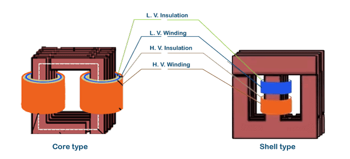
Most of the electronic devices or circuits used in today's world have different transformer applications. Therefore, it is significant to understand the definition, application, the working mechanism of transformers, and their end-to-end, construction in distinctive analog circuits. What is Transformer?The transformer is a static device used to step up and step down voltage levels, which works by transmitting electric current to a wire through a fluctuating magnetic field. However, when we learn briefer about transformers and associate it with electrical energy, we can define transformer as a static device that fluctuate the supply of voltage in different analog circuits. The transformer is a voltage regulator that is widely used in the circulation and conduction of ac (alternating current) supply. The concept of a basic transformer was first discovered by Michael Faraday in 1831 and later the idea was supported and developed by many other intellectual scientific researchers. 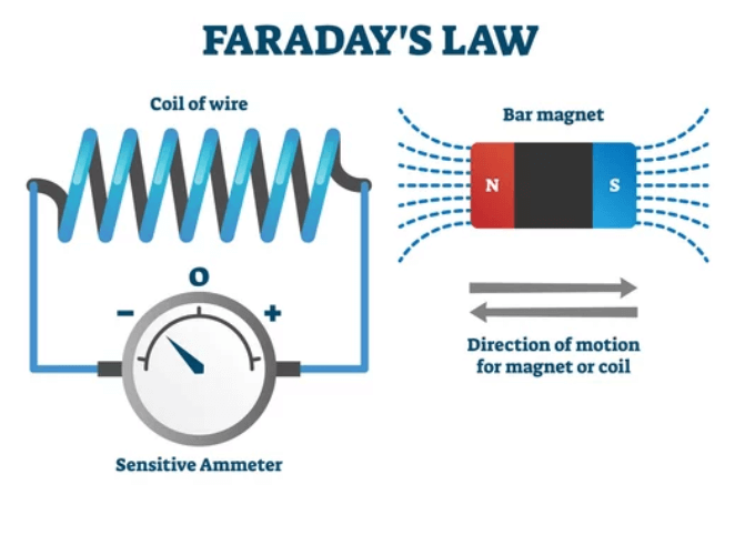
However, the generic motive of bringing the concept of transformers was to restore a balance between the current generated at high level voltages and its consumption which was done at low level voltages. Applications of TransformerThe applications of the transformer are as follows:
Working Principle of a TransformerThe mechanism of transformer's working has originated from the concept of Faraday's Law of Mutual Induction or Electromagnetic induction that occurs between two circuits connected by a mutual magnetic flux. Before heading on to the working of the transformer, let's discover the mechanism of electromagnetic induction. Mechanism of Electromagnetic InductionWhenever current passes through your electric wire coil, it produces a magnetic field or magnetic flux all across its surface. The magnetic flux or magnetic field for any material is defined as the temporary medium by which magnetized forces are transferred between electric materials. We often unknowingly encounter these forces in our day to day life, such as some ferromagnetic materials (iron, cobalt, or nickel) acts as temporary magnets in the presence of permanent magnets that pull and starts attracting or repelling other magnets or electric materials. However, the strength of the magnetic ?eld is directly proportional (is highly dependent) to the flow of the current in the wire. Therefore, one can easily manage, reverse, turn on or off, or vary the strength of a magnetic ?eld produced through the electric current. The magnetic field can be envisioned as outlines of magnetic flux that create closed paths. You can refer to the below figure to visualize the diagram of a magnetic field (flux lines) formed around a wire carrying an electric current. 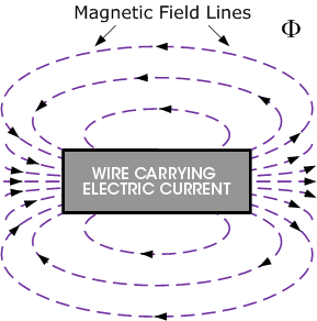
The concept of mutual induction does not end here. There's an additional interesting fact concerning electricity as well. Whenever a magnetic field changes across a coil of wire, it produces an electric current in the wire. Therefore, it allows us to generate a fluctuating magnetic flux by passing an electric current in a wire or coil (where the electric current is also fluctuating). Mutual Induction and Transformer
Step-down transformerIf the primary winding has more number of turns than the secondary winding, the second coil's voltage is less than the primary coil's voltage. This process is known as a step-down transformer. Step-up transformerTransforming the above process can develop a step-up transformer that raises a lower voltage into a higher one. With a set-up transformer, the number of turns in the secondary winding is more when compared to the primary. Therefore, it has a higher secondary voltage and a shorter secondary electric current. Transformer Construction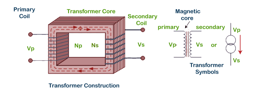
Here,
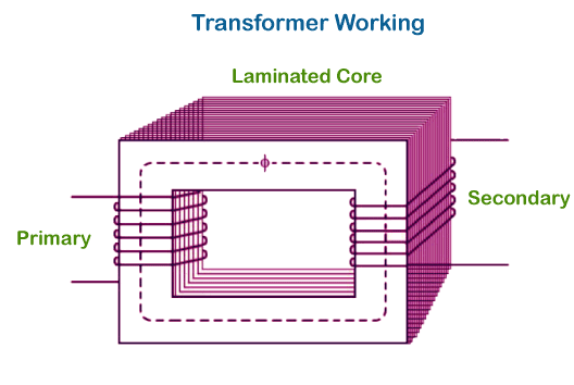
A transformer's fundamental construction is developed using two electric coil windings that carry mutual inductance and a laminated steel core. Both the coils (primary winding and the secondary winding) are insulated from one another and from the laminated core. The transformer set-up also requires some appropriate containers for the constructed core and windings, a mode with which the core and electric coils can be easily insulated. The major parts that every transformer contains are as follows: 1. CoreIn all transformers, the core acts as a support to the winding. It is created out of transformer sheet steel laminations built to deliver a steady magnetic path with the slightest air-gap integrated and lower down the transformer loss. The composition of a core is decided by factors, unlike effective voltage, current, power, etc. The diameter of the core is directly proportional (dependent) to copper losses and inversely proportional (inversely dependent) to iron losses. 2. WindingsWindings are defined as a set of copper wires coiled across the core. The copper wires are used in transformers because:
Primarily every transformer two types of windings, i.e., Primary windings and secondary windings, which are explained below:
Both the windings are insulated from each other with the help of insulation coating instruments. 3. Insulation AgentsInsulation is an essential process of transformers as it helps to insulate windings from shorting the circuit and therefore easing the electromagnetic induction. Insulation mediators affect the robustness and the firmness of a transformer. The various insulating agents used in a transformer are as follows:
Next TopicFibonacci Number
|
 For Videos Join Our Youtube Channel: Join Now
Feedback
- Send your Feedback to [email protected]
Help Others, Please Share


