| |

System Models in Software EngineeringIn software engineering, a system model is a procedure of creating abstract models to understand the system to be developed. It is an important step while creating software because, with the help of an abstract model, software developers can easily explain the system's structure and behaviour to customers. In this article, we will discuss the system models in software engineering. System ModelA system is a set of components related to each other and performing some functions. It is important to capture and keep in mind some key aspects. The key aspects are:
We can say that a system model is a procedure that represents the abstract view of the system with the help of graphical notation, which is based on notations in the UML (Unified Modeling Language). A system model contains a set of elements that have an interdependent relationship with each other. These models communicate with clients and explain the whole system to them. System PerspectivesThe abstract models represent a system from different perspectives:
Types of System Models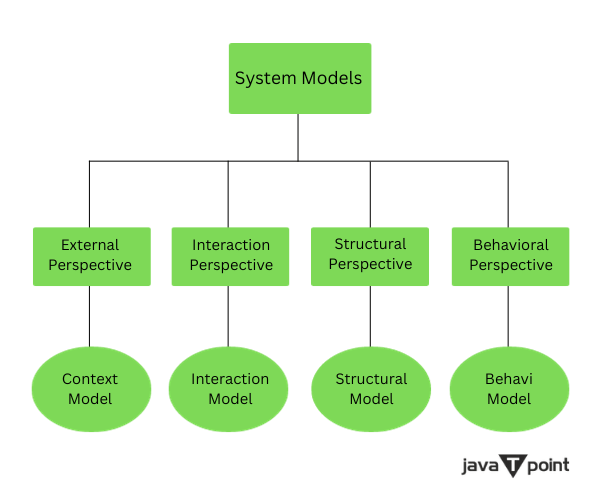
There are four types of system models, which are as follows: 1. Context Model:The external perspective model is a crucial step in developing software. The model shows how the system whose abstract view is being created is placed in an environment with the other system. In this step, software developers and stakeholders work together to decide the functionality to be included in the system. Whenever you use the system, there are so many surrounding systems that we need to deal with as their support is required, which means no software system is used in an isolated manner. It defines what lies outside the boundaries of the system. System boundaries are established to specify the outside and inside of the system. The position of the system boundary affects the system's needs. The purpose of the context model is to understand the environment in which the system will work, along with the support of the surrounding systems. Software developers develop various architectural models illustrating the system and its association with other systems. In simple words, we can say that the context model defines how the system interacts with its environment. Example of context model: The diagram below shows the main system at the centre, MHC-PMS (Mental Health Care Patient Management System). This system can be used in clinics and help them maintain patients' records. It comprises various sub-systems: the Patient Record System, Admission System, Prescription System, Appointments System, HC Statistics System, and Management Reporting System. These sub-systems are connected to the main system. These sub-systems support and work with the main system. 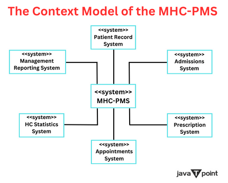
The Patient Record System maintains all the records related to the patient. The Admission System keeps the records of patients admitted. The Prescription System keeps track of all the medicines prescribed to the patient. The Appointment System helps make the appointments for the patients. The HC Statistics System provides analytical reports of the number of patients visited, the number of doctors, etc. The Management Reporting System generates and maintains the daily report of patients, a monthly report of patients, medicines prescribed and their dosage, etc. 2. Interaction Model:The interaction perspective model explains how components of the system interact with each other. There are three types of interactions:
There are two kinds of diagrams that come under interaction models, which are as follows: 1. Use Case Diagram: It was presented by Ivar Jacobson in 1987 in the article on use cases. It models interactions between a system and an external user or other system. It is a popular model used to support requirement elicitation and incorporated into the UML (Unified Modeling Language). It is a simple scenario to explain the user's needs from a system. Every use case shows a discrete task, including external system interaction. Example of the Use Case Diagram: In the simplest form, a "transfer-data" use case is shown below: 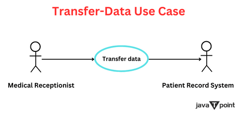
The use case is an ellipse, and the actors, i.e., users or other systems, are shown as a stick figure. The diagram shows a use case from MHC-PMS that we have discussed in the context model. The diagram has two actors: the Medical Receptionist and the Patient Record System. In the diagram, you can see that the medical receptionist is initiating the transaction, and data is transferred to the patient record system, i.e., it represents the task of uploading data to PRS (Patient Record System). The arrows in the UML indicate the flow of data. The receptionist must have the required security permissions to access the PRS. The data transferred from the main system MHC-PMS to a PRS could be the patient's personal information, treatment details, etc. For adequate understanding, you can elaborate on the same use case in the tabular format. Tabular description of the Transfer Data use case: 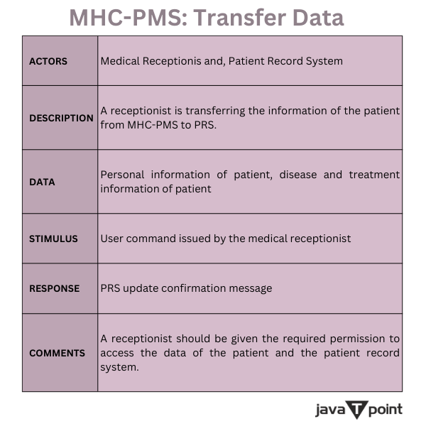
If there are many use cases, you can describe them using a composite use case diagram, showing various use cases in a single diagram. Composite Use Case Diagram: 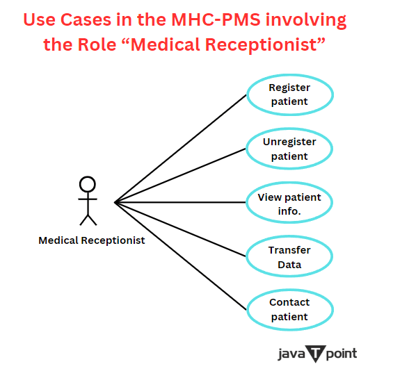
You can see the composite use case diagram above; there are five use cases: Register Patient, Unregister Patient, Transfer Data, View Patient Information, and Contact patient. All roles are played by the medical receptionist, which means the only actor is the medical receptionist, and there are five use cases. A receptionist looks at whether the patient is registered or unregistered; after that, the receptionist views the patient's information, such as contact, address, etc., then transfers the data and contacts the patient. 2. Sequence Diagrams: It is used to model interactions between system components, and external systems may also be involved. This diagram is useful in exhibiting the interaction between the actors and the objects within the system. It represents the sequence of interactions that take place at the time of a certain use case. Example of Sequence Diagram: You can see a sequence diagram below that is drawn to view patient information. This example has been taken from MHC-PMS, where viewing patient information is a type of functionality that MHC-PMS provides. We will see how the sequence diagram is drawn for viewing patient information, which means we will see the different sequences of interactions that will take place. 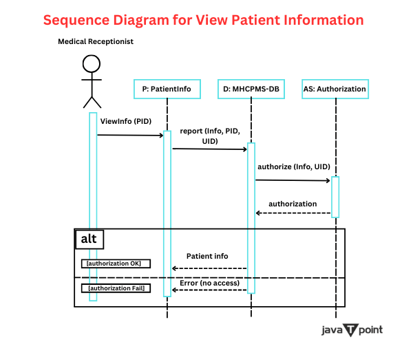
The sequence diagram shows interactions between actors and objects by annotated arrows. Solid annotated arrows represent the request, and the response is represented by dotted annotated arrows. Dotted lines are drawn below the objects to connect the different sequences of interactions. The top part of the diagram is listed with actors, i.e., medical receptionist and objects, i.e., patient info, MHCPMS database, and authorization. The interactions will occur if a medical receptionist wants to view the patient's information. The view patient information is not a single activity, but different interactions are hidden within the view patient activity. Initially, the medical receptionist sends a request along with the patient ID and PID to the object class "P: PatientInfo" to view information about the patient. From the instant "P" request is sent along with the PID (patient ID) and UID (user ID) to the database of MHC-PMS. From MHC-PMS, the information is not directly provided to the medical receptionist, but first authorization takes place to check whether the action is requested from an authorized user or not, as it is secure and private information that cannot be given to an unauthorized user that is why the request is sent to authorization object. A box named "Alt" shows whether the authorization is OK. If the user is authorized, only the patient information is returned from the database to "P: PatientInfo" and then to the medical receptionist. If the authorization fails, an error message says there will be no access to the information you are asking for. The vertical rectangular boxes represent the time of the object instant being active. The medical receptionist is active from the beginning to the end of the overall session, and the authorization is active for a short time. So, you can see, to view information, many sequences of interactions take place. All these things shown in the diagram help the developer design and implement these things and secure the system; that is why the sequence diagram is important. 3. Structural Model:The structural perspective model represents a system's organization in terms of the parts that build the system and their relationships. Structural models can be static models or dynamic models. The static models represent the structure of the system design, and the dynamic models represent the system's organization during execution. When we want to design the system architecture, then the structural model of the system is created. The structural model is of three types, which are as follows:
We will understand these types one by one. 1. Class diagrams It is a popular diagram that comes under UML. When creating an object-oriented system model, classes and their association are shown in the system, then class diagrams are used. An association is a relation between the classes that connect classes. Class diagrams are described at varying levels of detail in UML. An object class is a type of system object. UML classes and association: Let us understand how a class diagram is created. The class name is written inside the rectangular box, and the association between the two classes is shown with the help of a solid line. The feature of a class diagram is the ability to demonstrate the number of objects included in the association. You can see a simple diagram of patient and patient records below: 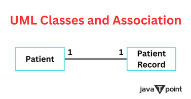
In the class diagram, the association between patient and patient records is one-to-one. Each end of the association is annotated with 1, which means one patient can have exactly one record. Classes and associations in the MHC-PMS In the diagram below, various classes are written inside the rectangular boxes. 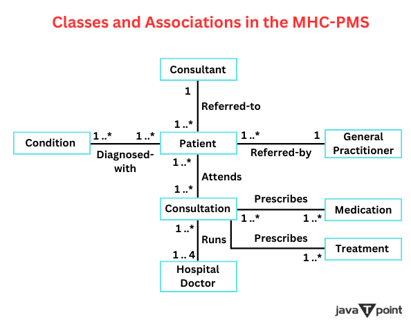
The classes are Condition, Consultant, Patient, General Practitioner, Consultation, Medication, Treatment, and Hospital Doctor. The diagram demonstrates the data entities, their associated attributes, and the relation between these entities. The association between classes should be shown easily. We can add more information about the attributes and operations of the class. We will see a diagram of adding more information to the class. Let us see the class "Consultation" attributes and operations in the class diagram. 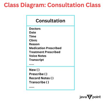
You can see the diagram above; a rectangle is divided into three parts. The object class is written in the top part of the rectangle, Class attributes are in the middle part, and operations are in the bottom. 2. Generalization It is the method that is used to manage the complexity. The entities are placed in more general classes for easy understanding. In object-oriented languages like Java, generalization is implemented with the help of class inheritance mechanisms built into the language. In generalization, the operations and attributes associated with higher-level classes are also associated with lower-level classes, which are subclasses that inherit the properties from parent classes. Example of Generalization Hierarchy: 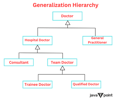
You can see the diagram above where the class, which is a more general class, is shown by using Arrowhead pointing up. Lower classes inherit all the operations and attributes from the parent classes. The higher level class is "Doctor". The lower level classes are "Hospital Doctor" and "General Practitioner", generalized as doctors. The "Consultant" and "Team Doctor" classes are generalized as hospital doctors. The "Trainee Doctor" classes and "Qualified Doctors" are generalized as team doctors. 3. Aggregation The UML delivers a special kind of relationship between classes called aggregation. Objects are composed of various parts, which the aggregation model shows. Example of aggregation association: In the diagram below, the "Patient Record" is an object class composed of Patients and Consultations. A diamond shape is used to show the composition of classes. 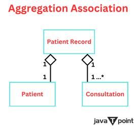
4. Behavioural Model:It is the behavioural perspective model that represents the dynamic behaviour of the system. There are two types of behavioural models:
Let us comprehend both types in detail one by one. 1. Data-driven modeling It means data that comes in has to be processed by the system. Data-driven modes are the first graphical software models. Data-driven models represent the actions, which include processing input data and generating an associated output. These models are used to show end-to-end processing in the system, so they are helpful for analysis of requirements. Data Flow Diagrams (DFDs) are simple diagrams for tracking and documentation purposes. It helps to understand the developers of the system. It shows the data exchange between a system and other systems within its environment. Example of an activity model of an insulin pump's operation: The diagram below shows an activity model of the insulin pump's operation. You can see the processing steps in the diagram below. The data flowing between these steps is represented as objects. You already know that it is a sequence diagram used to model interaction. 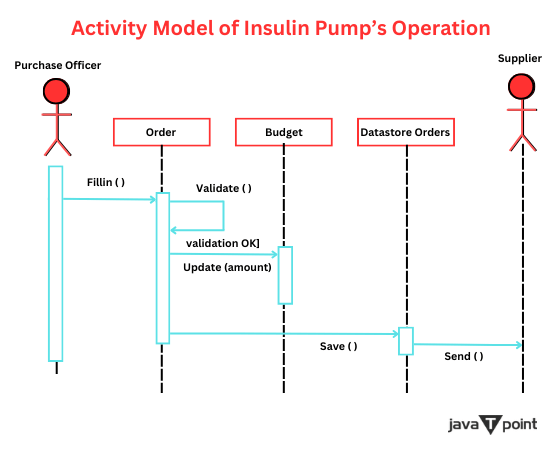
Example for order processing DFD for insulin pump: The order processing DFD for the insulin pump is shown in the diagram below. In this example, notations used in this model are the rounded boxes for representing the functional boxes, rectangular boxes for representing the data stored, and arrows for representing the data flow between the functions. 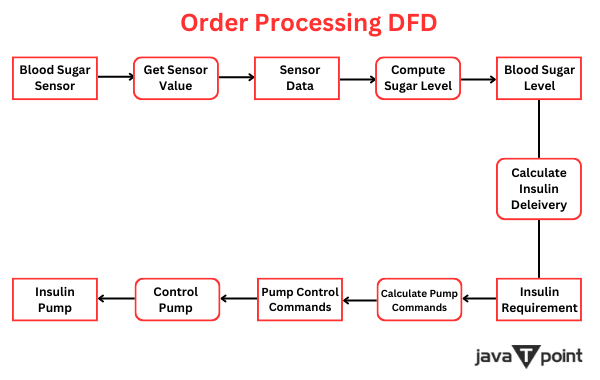
Blood Sugar is taken in this example and then analyzed through the sensor. After that, according to the blood sugar, the required insulin computation is done, and the proper amount of insulin is given to the patient to control the sugar level. The data flows in a systematic way to achieve the goal. 2. Event-driven modeling It means that an event occurs that triggers the system, and that event may have associated data. This model represents the response of the system to external and internal events. This modeling assumes a system has several states, and events can cause transitions between states. It is used to depict the state machine model. The state machine model represents system states as nodes and events as arcs between these nodes. Event-driven modeling is represented with the help of state diagrams, which are based on state charts. Example of State Diagram: You can see a state diagram of a microwave oven below, but real microwaves are much more complex than this state diagram. 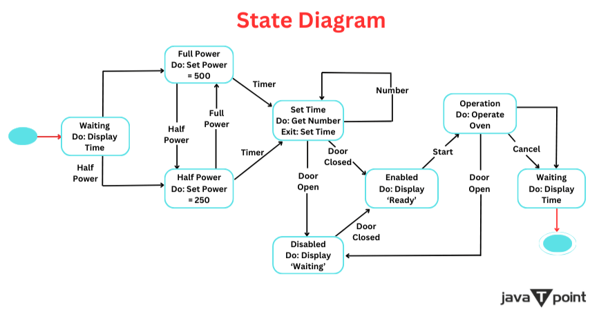
In this example, a simple microwave is used to understand the state diagram easily. A microwave has a switch for selecting half or full power, a numeric keypad for inputting the cooking time, an alphanumeric display, and a start-stop button. The display shows half power when the microwave oven power is 250 watts. The display shows full power when the microwave oven power is assigned to 500 watts. We have assumed the sequence of actions in the microwave in the following order: the first sequence is to select the power level, either half or full; the second sequence is to input the cooking time with the help of an alphanumeric keypad, and then the third sequence is to press the start button. After that, there will be two conditions: "Door Open" and "Door Closed". If the door is open, then the operation is disabled. If the door is closed, the timer is set, and the operation is enabled. When the microwave starts, cooking takes place for a specific time. After the cooking time is over, a buzzer sounds, and the microwave display returns to the waiting state. Conclusion
|
 For Videos Join Our Youtube Channel: Join Now
Feedback
- Send your Feedback to [email protected]
Help Others, Please Share


